Hyundai Santa Cruz: Audio/AVNT System / AVN Head Unit
| No | Connector A (ExternalAmplifier) | Connector A (Internal Amplifier) | Connector B | Connector C |
| 1 | - | Rear door speaker LH (+) | Mic2 (+) | - |
| 2 | - | Rear door speaker LH (-) | Mic1 (+) | I -CAN (High) |
| 3 | Navigation voice (+) | - | - | - |
| 4 | External amplifier SPDIF (+) | - | - | - |
| 5 | Reset | Reset | - | - |
| 6 | Camera power | Camera power | Illumination (+) | - |
| 7 | Camera video | Camera video | M-CAN (High) | - |
| 8 | - | - | - | - |
| 9 | - | - | - | I -CAN (Low) |
| 10 | - | - | Battery (+) | - |
| 11 | DETECT | DETECT | Battery (+) | - |
| 12 | Steering wheel remote | Steering wheel remote | Ground | - |
| 13 | - | Front door speaker LH (+) | Ground | - |
| 14 | - | Front door speaker LH (-) | Mic2 (-) | - |
| 15 | - | Front door speaker RH (-) | Mic1 (-) | - |
| 16 | - | Front door speaker RH (+) | - | MTS |
| 17 | Navigation voice (-) | - | - | - |
| 18 | External amplifier SPDIF (-) | - | - | - |
| 19 | External amplifier SPDIF (Ground) | - | Illumination (-) | - |
| 20 | Camera power ground | Camera power ground | M-CAN (Low) | - |
| 21 | Camera video ground | Camera video ground | - | - |
| 22 | - | - | ACC | |
| 23 | - | - | Keyboard power | |
| 24 | - | - | Front monitor power | |
| 25 | - | - | - | |
| 26 | Steering wheel remote ground | Steering wheel remote ground | - | |
| 27 | - | Rear door speaker RH (-) | - | |
| 28 | - | Rear door speaker RH (+) | - | |
| 29 | - | - | - | |
| 30 | - | - | - | |
| 31 | - | - | - | |
| 32 | Camera Detect (RVM : - / SVM : Ground) | Camera Detect (RVM : - / SVM : Ground) | - | |
| 33 | Camera shield ground | Camera video shield | IGN 1 | |
| 34 | - | - | Keyboard ground | |
| 35 | - | - | Front monitor ground | |
| 36 | - | - | ||
| 37 | - | - | ||
| 38 | Vehicle speed | Vehicle speed |
1.Disconnect the negative (-) battery terminal.
2.Remove the front monitor lower cover (A).
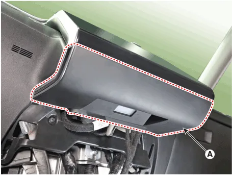
3.Remove the front monitor lower cover after disconnecting the mood lamp connector (A).
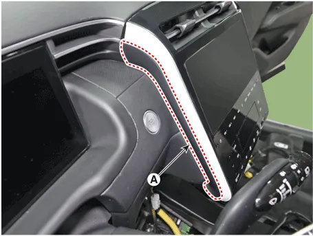
4.Remove front monitor side cover (A) and (B).

5.Remove the front monitor assembly (A).
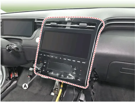
6.Remove the front monitor assembly (A) after disconnecting monitor connectors.
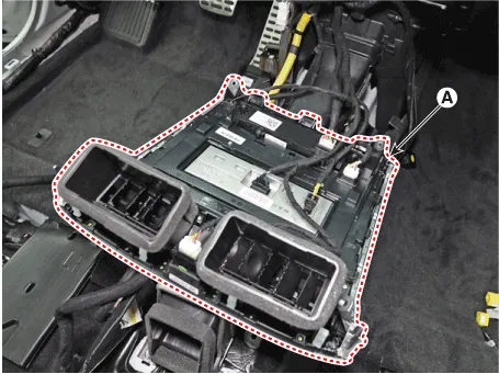
7.Remove the AVN head unit after loosening mounting screws.
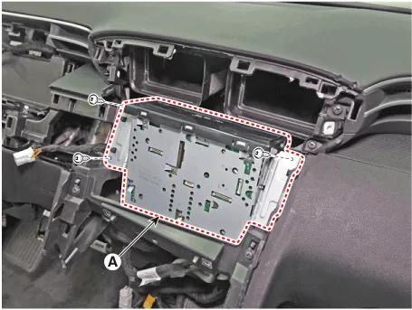
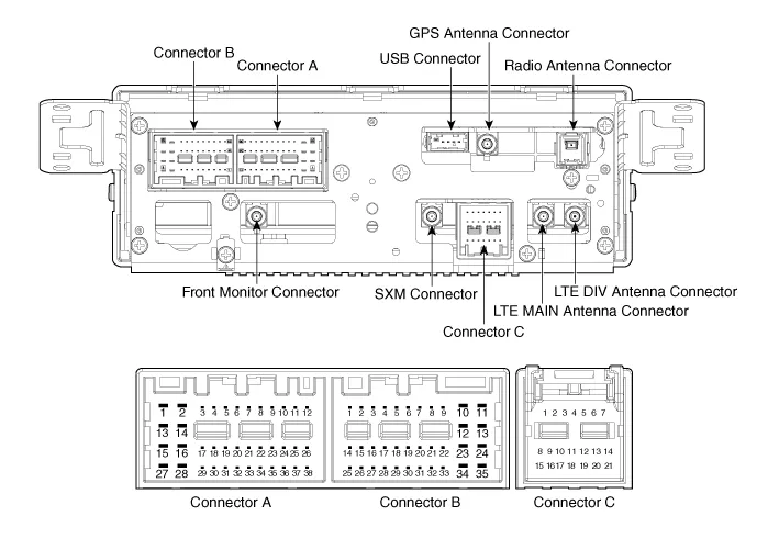
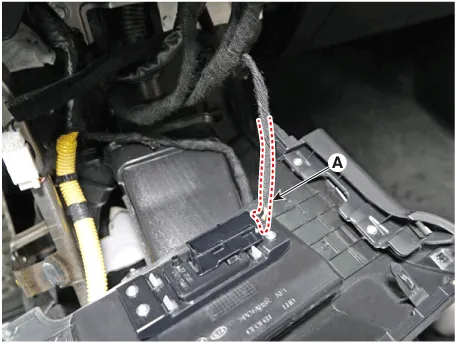
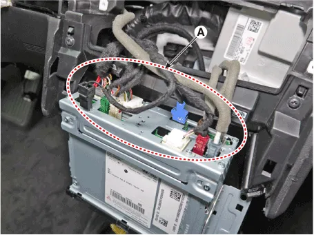
8.Remove the AVN head unit after disconnect audio connectors (A).
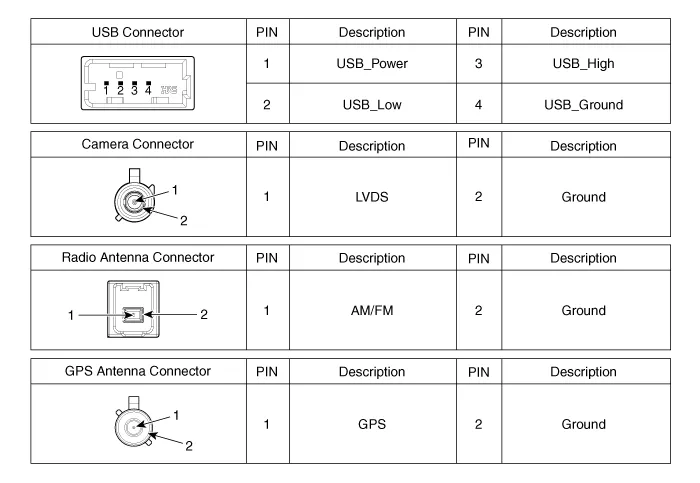
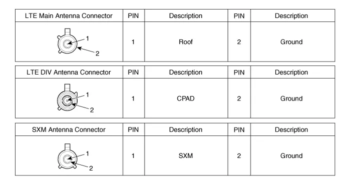
1.Install AVN head unit connectors and antenna connectors.
2.Install the AVN head unit.
3.Install the front monitor assembly.
4.Install the front monitor side cover.
5.Install the front monitor lower cover.
6.Connect the negative (-) battery terminal.

• Make sure the connector are connected in properly.
• Check the AVN system for normal operation.
 Specifications
- Specifications
ItemSpecification
Power sourceDC 14.4V (-) ground
Frequency range / Channel spaceFM : 87.5 - 108.0 MHz / 100 KHzAM : 531 - 1602 KHz / 9 KHz
Tuning typePLL SYNTHESIZED TUNING
Im ...
 Display Audio Unit
- Components
NoConnector A (Internal Amplifier)Connector A (External Amplifier)Connector BConnector C
1Rear door speaker LH (+)- --
2Rear door speaker LH (-)- Mic1 (+) I -CAN (High)
3-Navigat ...
Other information:
Hyundai Santa Cruz (NX4A OB) 2021-2025 Service Manual: Description and Operation
- Description
Rear Corner Radar is a system that measures the relative speed and
distance from the following vehicles by using two electromagnetic wave
rear corner radar sensors attached to the rear bumper, and detects any
vehicle within the blind spot zone and gives off alarm.System Interf ...
Hyundai Santa Cruz 2021-2025 Owners Manual: Hyundai Digital Key
Digital Key Application
To use Hyundai Digital Key mobile app,
you should install the Hyundai Digital
Key app on your Android phone. Search
‘Hyundai digital key’ in the Google Play
Store and download the app. Please refer
to the detailed manual of the digital key
app. The option can be fou ...
