Hyundai Santa Cruz: Heater / PTC Heater
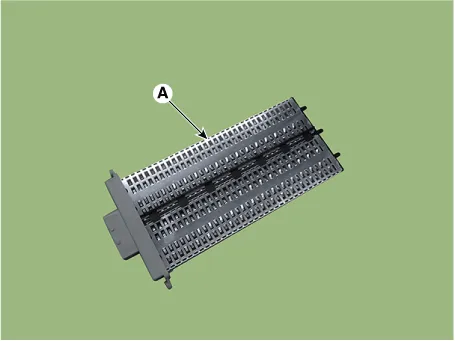
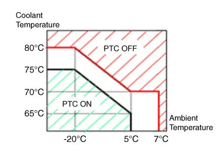
• Battery voltage : 13V or above
• Engine : Running
• Ambient temperature and coolant temperature
1.Entering
(1)Set the mode to FLOOR.
(2)Set the temperature to MAX HOT.
(3)Turn off the blower switch.
(4)Press the intake (recirculation) button 5 times or more.
2.Forced operation
(1)Non-A/C : The intake button indicator will blink with an interval of 0.5 second for 30 seconds.With A/C : The intake and A/C button indicator will blink with an interval of 0.5 second for 30 seconds.
(2)The PTC2 and PTC3 will operate by turning on the blower switch.
– The PTC will operate by turning on the blower switch.
– The PTC will turn off simultaneously when the blower switch is turned off.
3.Cancellation
(1)Select A/C or intake (recirculation) switch.
(2)The test cancels automatically after 30 seconds.
(3)Turn the ignition switch off.
1.Run the engine.
2.Check the current on the wiring with a clamp multi tester.
| Pattern | Current (A) |
| PTC 1 ON | 0.1 ~ 49 |
| PTC 2 ON | 0.1 ~ 49 |
| Total | 0.1 ~ 100 |
3.If the current is not within specification, inspect the related wiring.
1.Turn the ignition switch OFF.
2.Disconnect the PTC heater connector.
3.Measure the resistance between terminal 1, 2 of PTC heater and ground line.
Resistance : 0.3 - 1.5Ω
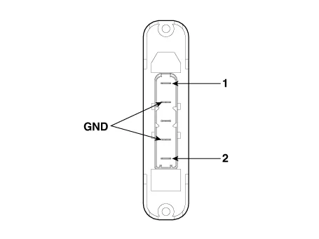
1)PTC 1
2)PTC 2
4.If the measured resistance is not within specification, replace the PTC heater with a new one.
1.Disconnect the negative (-) battery terminal.
2.Remove the heater and blower assembly.(Refer to Heater - "Heater Unit")
3.Loosen the mounting screws and remove the PTC heater (A).
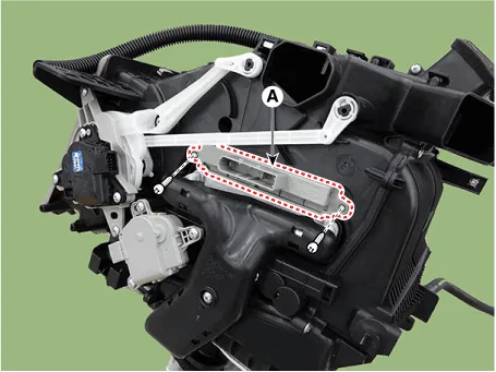
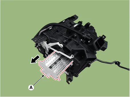
4.Install in the reverse order of removal.

• Make sure the connector is connected properly.
 Evaporator Core
- Replacement
1.Disconnect the negative (-) battery terminal.
2.Remove the heater core.(Refer to Heater - "Heater Core")
3.Loosen the mounting screws and remove the evaporator core cover (A).
...
 Temperature Control Actuator
- Description
The heater unit includes mode control actuator and temperature control
actuator.The temperature control actuator is located at the heater unit.
It regulates the temperature by the ...
Other information:
Hyundai Santa Cruz (NX4A OB) 2021-2025 Service Manual: Dual Clutch Transmission System
- Components and Components Location
1. Dual clutch transmission2. Transmission mounting bracket3. Position switch4. Shift cable bracket5. Dual clutch transmission control module (TCM)6. High Flow Electric Oil Pump (HF EOP)7. Oil cooler module8. Accumulator
- Removal
...
Hyundai Santa Cruz (NX4A OB) 2021-2025 Service Manual: Rear Console Cover
- Component Location
1. Rear console cover
- Replacement
• When removing with a flat-tip screwdriver or remover, wrap protective tape around the tools to prevent damage to components.
• Put on gloves to prevent hand injuries.
• Take c ...
