Hyundai Santa Cruz: Crash Pad / Crash Pad Center Panel
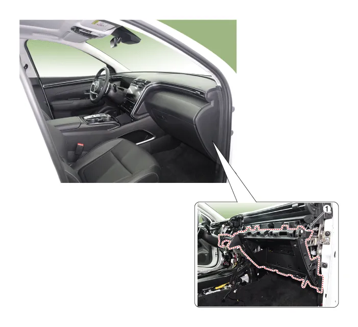
1. Crash pad center panel

• When prying with a flat-tip screwdriver, wrap it with protective tape, and apply protective tape around the related parts, to prevent damage.
• Put on gloves to protect your hands.

• Take care not to bend or scratch the trim and panels.
1.Remove the floor console assembly.(Refer to Floor Console - "Floor Console Assembly")
2.Remove the crash pad under cover.(Refer to Crash Pad - "Crash Pad Under Cover")
3.Remove the glove box.(Refer to Crash Pad - "Glove Box")
4.Remove the front monitor.(Refer to Body Electrical System - "Front Monitor")
5.Remove the crash pad lower panel.(Refer to Crash Pad - "Crash Pad Lower Panel")
6.Remove the crash pad garnish[RH].(Refer to Crash Pad - "Crash Pad Garnish")
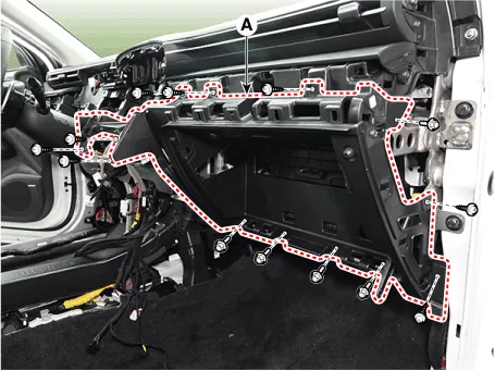
7.Loosen the mounting screws, bolts and nuts, remove the crash pad center panel (A).
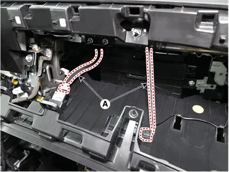
8.Disconnect the connectors (A).
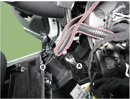
9.Disconnect the in-car sensor connector (A) and hoses (B).
10.To install, reverse removal procedure.

• Make sure the connector are connected in properly.
• Replace any damaged clips.
 Crash Pad Under Cover
- Replacement
• When prying with a flat-tip screwdriver, wrap it with protective
tape, and apply protective tape around the related parts, to prevent
damage.
• Put on ...
 Main Crash Pad Assembly
- Component Location
1. Main crash pad assembly
- Replacement
• When removing with a flat-tip screwdriver or remover, wrap protective tape around the tools to prev ...
Other information:
Hyundai Santa Cruz 2021-2025 Owners Manual: Manual Heating and Air
Conditioning
1. Start the engine.
2. Set the mode to the desired position.
For improving the effectiveness of
heating and cooling, select:
- Heating:
- Cooling:
3. Set the temperature control to the
desired position.
4. Set the air intake control to the
outside (fresh) air position.
5. Set the fan speed co ...
Hyundai Santa Cruz (NX4A OB) 2021-2025 Service Manual: Repair procedures
- Removal
1.Disconnect the negative (-) battery terminal.
2.Remove the heater control unit.(Refer to Heating, Ventilation And Air Conditioning - "Heater Control Unit")
3.Remove the IBU (A) after loosening mounting bolt, nut and screw.
4.Disconnect IBU connectors and then remove the IBU (A) ...
