Hyundai Santa Cruz: Engine And Transaxle Assembly / Engine Mounting
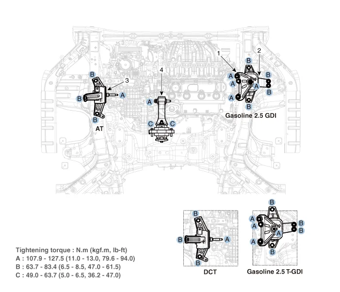
1. Engine mounting support bracket
2. Engine mounting bracket
3. Transaxle mounting bracket
4. Roll rod bracket
1.Remove the engine room under cover.(Refer to Engine And Transaxle Assembly- "Engine Room Under Cover")
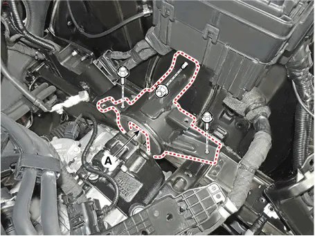
2.Remove the roll rod bracket (A).
Tightening torque Bolts (B) : 49.0 - 63.7 N.m (5.0 - 6.5 kgf.m, 36.2 - 47.0 lb-ft)Bolt (C) : 107.9 - 127.5 N.m (11.0 - 13.0 kgf.m, 79.6 - 94.0 lb-ft)
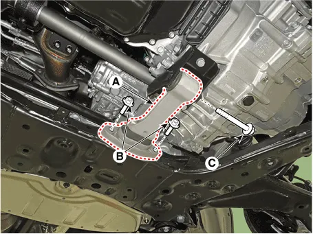

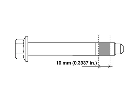
• The through bolt shall be replaced with freshness or applied with adhesive (3M 2353) to the bolt mark as shown below and then mounted as a tightening torque.
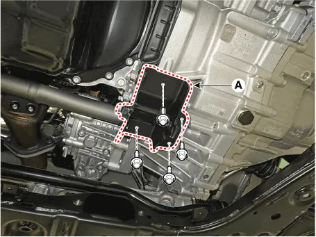
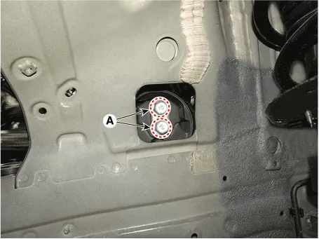
3.Remove the roll rod mounting support bracket (A).
Tightening torque :49.0 - 68.6 N.m (5.0 - 7.0 kgf.m, 36.2 - 50.6 lb-ft)
4.Install in the reverse order of removal.
1.Remove the engine room under cover.(Refer to Engine And Transaxle Assembly- "Engine Room Under Cover")
2.Install the jack to the edge of oil pan to support the engine.

• Insert the rubber block between jack and oil pan.
3.Remove the engine mounting support bracket (A).
Tightening torque :107.9 - 127.5 N.m (11.0 - 13.0 kgf.m, 79.6 - 94.0 lb-ft)
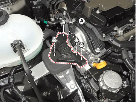
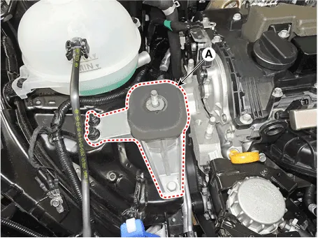
4.Remove the engine mounting bracket (A).
Tightening torque : 63.7 - 83.4 N.m (6.5 - 8.5 kgf.m, 47.0 - 61.5 lb-ft)
5.Install in the reverse order of removal.

• Note the following items when working on the engine mounting bracket and the engine mounting support bracket.
• Always use a new engine mounting bracket and engine mounting support bracket securing nut.
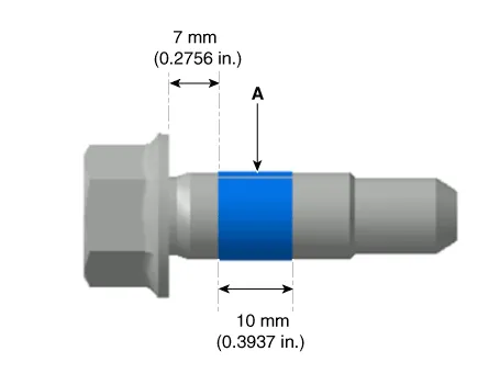
• Use a new bolt for fixing the engine mounting bracket or apply adhesive to the section of the bolt (A) as shown below.
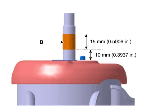
• When installing the engine mounting support bracket-Clean the hardened adhesive on the engine mounting bracket stud (B).-Reapply the adhesive to the engine mounting bracket studs (B) as shown below.
1.Remove the air duct and air cleaner assembly.(Refer to Intake And Exhaust System - "Air Cleaner")
2.Remove the engine control module (ECM).(Refer to Engine Control / Fuel System - "Engine Control Module (ECM)")
3.Remove the battery and battery tray.(Refer to Engine Electrical System - "Battery")
4.Remove the engine room under cover.(Refer to Engine And Transaxle Assembly - "Engine Room Under Cover")
5.Install the jack to the edge of transaxle.

• Insert the rubber block between jack and oil pan.
6.Remove the LH front wheel guard.(Refer to Body(Interior and Exterior) - "Front Wheel Guard")
7.Remove the transaxle mounting bolts (A).
Tightening torque : 107.9 - 127.5 N.m (11.0 - 13.0 kgf.m, 79.6 - 94.0 lb-ft)
8.Remove the transaxle mounting bracket (A).
Tightening torque : 63.7 - 83.4 N.m (6.5 - 8.5 kgf.m, 47.0 - 61.5 lb-ft)
9.Install in the reverse order of removal.
 Engine Room Under Cover
- Removal and Installation
1.Remove the engine room under cover (A).Tightening torque :7.8 - 11.8 N.m (0.8 - 1.2 kgf.m, 5.8 - 8.7 lb-ft)
2.Install in the reverse order of removal. ...
 Engine And Transaxle Assembly
- Removal and Installation
• Use fender covers to avoid damaging painted surfaces.
• To avoid damage, unplug the wiring connectors carefully while holding the connector ...
Other information:
Hyundai Santa Cruz (NX4A OB) 2021-2025 Service Manual: Warning and Caution Labels
- Warning and Caution Labels
1. Radiator cap caution
2. Fan caution
3. Battery caution
Battery Caution Label
Warning / Caution Label (Cont'd)
A.
Keep lighted cigarettes and all other flames or sparks away from the battery.
...
Hyundai Santa Cruz (NX4A OB) 2021-2025 Service Manual: Auto defoging sensor
- Description
The auto defogging sensor is installed on the front window glass. The
sensor judges and sends signal if moisture occurs to blow out wind for
defogging. The air conditioner control module receives signal from the
sensor and restrains moisture and eliminate defog by controlling ...
