Hyundai Santa Cruz: Front Radar System / Front Radar Unit
| Item | Specification |
| Power supply (V) | 12 |
| Operation voltage (V) | 9 - 16 |
1.Check the bumper appearance for accident (check the vehicle appearance visually and see bumper replacement history).☞ In case of the vehicle was involved in an accident, there is a high possibility that the FCA radar is out of the original default position.
2.Check for contamination of the radar sensor cover of the bumper.☞If contaminated, there is a high possibility that the FCA system is deactivated during operation due to the foreign substances.
3.After turning on the engine, check the FAC warning lamp and DTC.(Refer to the DTC diagnosis guide.)
1.Turn ignition switch OFF and disconnect the negative (-) battery cable.
2.Remove the front bumper assembly.(Refer to Body - "Front Bumper Assembly")
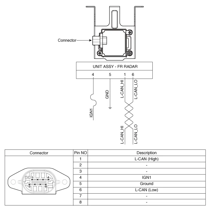
3.Disconnect the front radar connector (A).
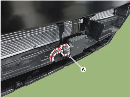
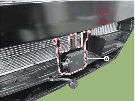
4.Loosen the mounting nuts and remove the front radar (A).
Front radar nuts : 6.79 - 7.5 N·m (0.69 - 0.76 kgf·m, 5.0 - 5.5 lb·ft)
1.To install, reverse the removal procedure.

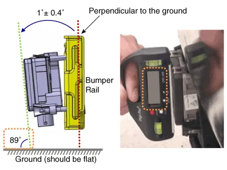
• The vertical installation angle of the unit must be within 1˚ ± 0.4˚. (not 0 degree)※ Before installing the bumper onto the vehicle, measure the vertical angle of the unit with a protractor as shown.
2.Connect the GDS to Data Link Connector (DLC).
3.Switch "ON" the ignition.
4.Select "Vehicle, Model year, Engine, System".
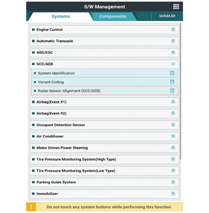
5.Select "Vehicle S/W Management".

• The FCA unit has been reinstalled or replaced with a new one.
• The radar sensor or the surrounding parts have been impacted by collision.
• The sensor cannot detect a vehicle in front.
• The Steering Angle Sensor (SAS) has been replaced or adjusted.

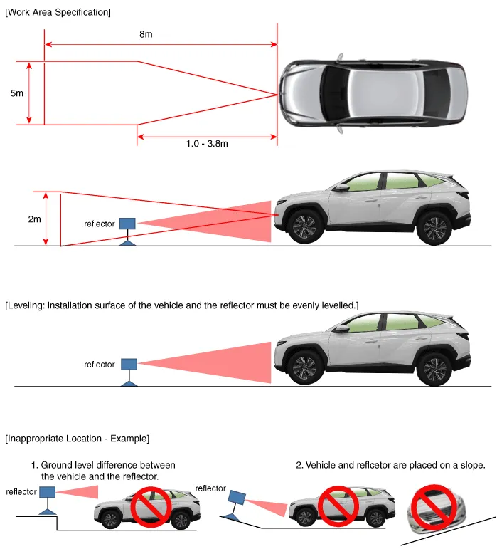
• Park the vehicle on a level ground.
• Set all tires according to the specified pressure.
• Check wheel alignment.
• Check that the front surface of the FCA unit is clean.

• Adjustment may not be accurate if the vehicle and reflector are placed on different ground levels or on a slope.
• Perform in an area with minimum clearance of 8 m to the front, 4 m wide, and 1.2 m above the ground.
• Remove heavy objects from inside of the vehicle (seating area and trunk).
• Ensure that all tires are filled with specified air pressure.
• Remove objects (metal plates, resins, etc.) that may cause electric signal interference from the area where sensor alignment is performed.
• Be sure that the vehicle is not moved and free from vibration when performing sensor alignment (getting in/out or opening/closing doors).
• Check that radiator grille and sensor cover are not dirty.
• Check for correct wheel alignment.
• Do not turn OFF the power when performing sensor alignment.
• Power supplied to the radar sensor must be between 9V - 16V.
• Temperature in the area where sensor alignment is performed must be between -30 - 60°C.
1.Park the vehicle on a level ground.
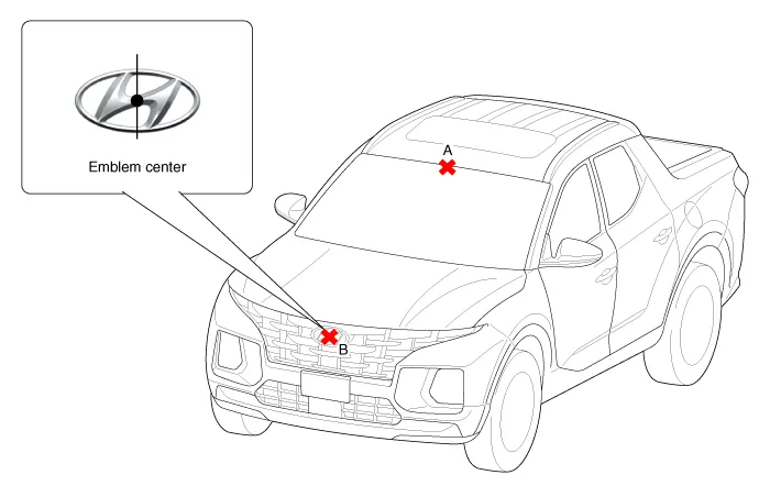
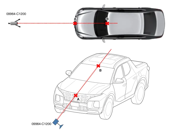
2.Mark the center point on top of windshield glass (A).
3.Mark the center point of emblem (B).
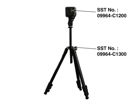
4.Mount the FCA Calibration Laser [SST No. : 09964-C1200] onto the tripod [SST No. : 09964-C1300].
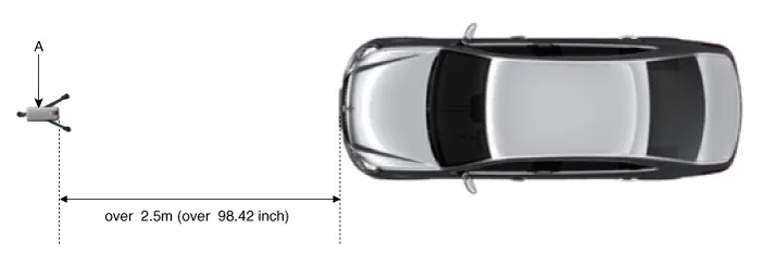
5.Install the vertical/horizontal laser [SST No. : 09964-C1200] (A) at least 2.5 m to the front of the vehicle.
6.Match the vertical line of laser to (A) and (B) using the vertical/horizontal laser (C) [SST No. : 09964-C1200].
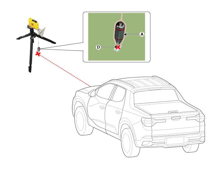
7.Mark (C) at 2.3 - 2.5m (90.55 - 98.42 inch) from (A) in front of the vehicle.
8.Mark (D) at the place which is 19 mm away from (C) to the passenger direction.
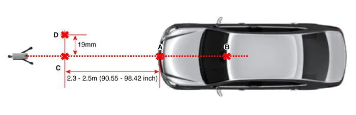

• If possible, perform calibration at the 2.5m position.
9.Remove the FCA Calibration Laser [SST No. : 09964-C1200] (B) from the tripod [SST No. : 09964-C1300] (A).
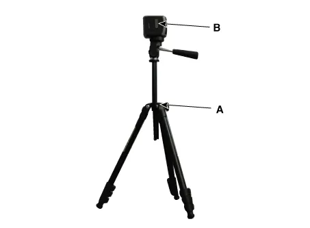
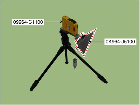
10.Mount the reflector [SST No. : 09964-C1100] (B) onto the tripod [SST No. : 09964-C1300] (A).
11.Mount the reflector adapter (0K964-J5100) to the reflector (09964-C1100).
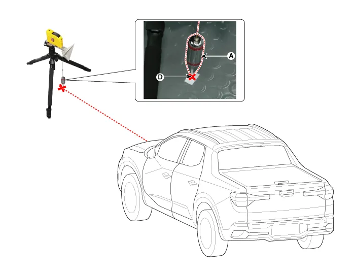
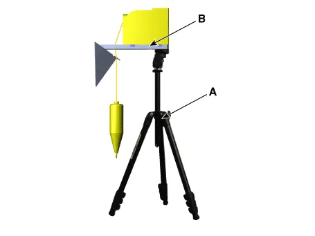
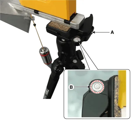
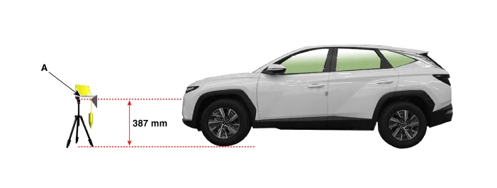
12.Align the vertical weight (A) of the FCA Calibration Reflector [SST No. : 09964-C1100] with the point (D).
13.Using the bubble level (B) of the tripod [SST No. : 09964-C1300] (A), set the reflector horizontally.
14.Set the height of the FCA calibration reflector [SST No. : 09964-C1100] (A) to 387 mm (15.23 inch).
15.Visually check again the radar sensor and the surface of the front bumper for the following.

• Make sure that there is no debris, or reflecting object on the surface of the front radar.
• Make sure that there is no debris, or reflecting object on the radiator grille.
16.Connect the GDS to the DLC of the vehicle and start sensor alignment.

• If the engine is running, the vibration may cause inaccurate sensor alignment, so perform sensor alignment in IG ON mode.
17.After correctly selecting the vehicle model, select "FCA Alignment" from the auxiliary functions in diagnostic tool Menu.
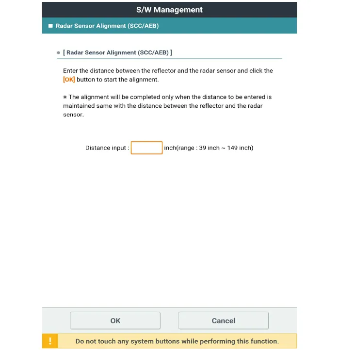
18.Perform sensor alignment as indicated on the diagnostic tool monitor.
19.In case of sensor alignment failure, check the alignment conditions. Turn the ignition key OFF, then reperform the sensor alignment procedure.
 Components and Components Location
- Components Location
1. Front radar unit2. Smart cruise control switch
...
 Smart Cruise Control (SCC) Switch
- Components
1. Remote control switch (LH : Audio)2. Remote control switch (RH : Trip + Cruise)
- Circuit Diagram
Trip+SCC+MSLA+LFA
- Inspection
1.Check for resistance between te ...
Other information:
Hyundai Santa Cruz (NX4A OB) 2021-2025 Service Manual: Side Impact Sensor (SIS)
- Description
1.The Side Impact Sensor (SIS) system consists of two kinds of side
impact sensor which are installed at each center of the front door
module (left and right) and two rear sensors which are installed in the
rear pillar (left and right). • The Front Side Impact Sensor is also ...
Hyundai Santa Cruz (NX4A OB) 2021-2025 Service Manual: TPMS Receiver
- Description
TPMS Receiver : BCM(body control module) integrated management
1.Mode(1)Virgin State • The receiver as a sole part is shipped in this state. Replacement parts should therefore arrive in this state.
• In this state, there is no Auto-Location, no sensor wake-up, no sensor mo ...
