Hyundai Santa Cruz: Controller / Heater Control Unit
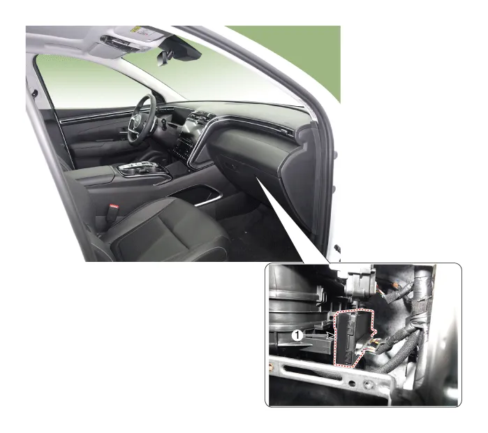
1. Heater control unit
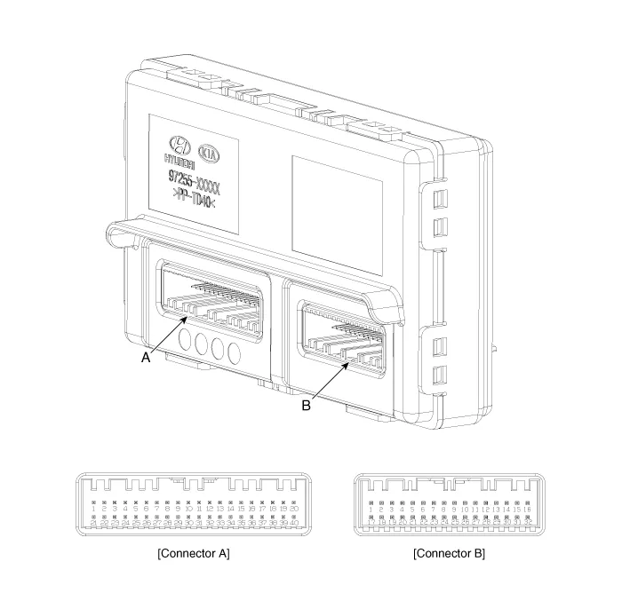
| Pin No | Connector A | Connector B |
| 1 | Mode control actuator feedback | Ground |
| 2 | Intake actuator feedback | Sensor ground |
| 3 | Passenger's temperature control actuator feedback | ECV (-) |
| 4 | Driver's temperature control actuator feedback | ECV (+) |
| 5 | Auto defogging actuator feedback | - |
| 6 | - | - |
| 7 | - | - |
| 8 | Photo sensor (-) LEFT | Blower INH |
| 9 | Photo sensor (-) RIGHT | Blower IS |
| 10 | - | Blower PWM IN |
| 11 | Auto defogging actuator SDA | - |
| 12 | Auto defogging actuator SCL | - |
| 13 | Auto defogging actuator TEMP | Sensor (+ 5V) |
| 14 | Ambient temperature sensor (+) | - |
| 15 | Evaporator sensor (+) | - |
| 16 | - | Battery (+) |
| 17 | - | Ground |
| 18 | - | - |
| 19 | - | - |
| 20 | - | - |
| 21 | Mode control actuator (Vent) | - |
| 22 | Mode control actuator (DEF) | - |
| 23 | Intake actuator (FRE) | - |
| 24 | Intake actuator (REC) | - |
| 25 | Passenger's temperature control actuator (Cool) | Blower operation signal |
| 26 | Passenger's temperature control actuator (Warm) | - |
| 27 | Driver's temperature control actuator (Cool) | PTC Relay |
| 28 | Driver's temperature control actuator (Warm) | - |
| 29 | Auto defogging actuator (Open) | Blower relay |
| 30 | Auto defogging actuator (Close) | LIN BUS (Climate control) |
| 31 | - | IGN1 |
| 32 | - | IGN2 |
| 33 | - | |
| 34 | E_CAN (Low) | |
| 35 | E_CAN (High) | |
| 36 | - | |
| 37 | - | |
| 38 | - | |
| 39 | - | |
| 40 | Ground |
1.Disconnect the battery (-) terminal.
2.Remove the glove box.(Refer to Body (Interior and Exterior) - "Glove Box")
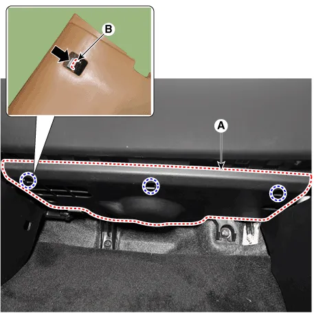
3.Press the lock pin (B) and then remove the crash pad under cover (A).
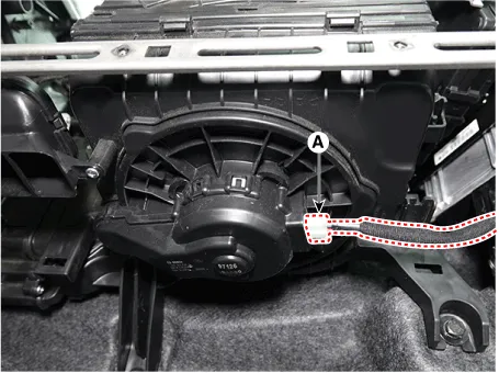
4.Disconnect the blower motor connector (A).
5.Remove the heater control unit (A), after removing the screws.
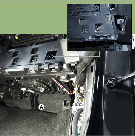
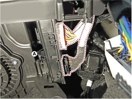
6.Disconnect the heater control unit connector.
7.Install in the reverse order of removal.

• Make sure the connector is connected properly.
 Heater & A/C Control Unit (DATC)
- Terminal Function
Connector Pin Function
Pin NoConnector A
1Battery (+)
2-
3-
4LIN BUS (Climate control)
5-
6-
7-
8-
9IGN2
10ISG B+
11IGN1
12-
13Incar sensor (+)
14-
15Sensor G ...

Other information:
Hyundai Santa Cruz (NX4A OB) 2021-2025 Service Manual: Steering Gear Box
- Components
1. Tie rod end2. Steering gear box
- Removal
• When lifting a vehicle using a lift, be careful not to damage
the lower parts of the vehicle (floor under cover, fuel filter, fuel
tank, canister).(Refer to General Information - "Lift and Support
Po ...
Hyundai Santa Cruz (NX4A OB) 2021-2025 Service Manual: Repair procedures
- Replacement
• When removing the fender, wrap protective tape around a screwdriver or remover not to damage components
• Put on gloves to prevent hand injuries
1.Remove the front bumper.(Refer to Front Bumper - "Front Bumper Assembly")
2.Remove the head lamp.(Refe ...
