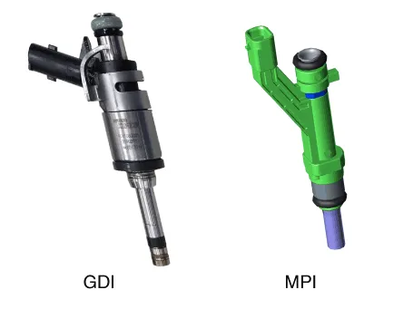
Hyundai Santa Cruz: Engine Control System / Injector
| Item | Specification |
| Coil Resistance (Ω) | 1.42 - 1.58 [20°C (68°F)] |
| Item | Specification |
| Coil Resistance (Ω) | 11.4 - 12.6 [20°C (68°F)] |
1.The engine control system can be more quickly diagnosed for troubles by using the vehicle diagnostic system. (Refer to "DTC guide")
(1)diagnostic tool : Check and display fault codes (DTC).
(2)Sensor dater : Check System I/O Value Status.
(3)Forced drive : Check the system operation.
(4)Additional Functions : Control of other functions such as system options and zero control.
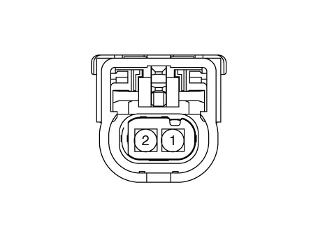
1.Turn the ignition switch OFF.
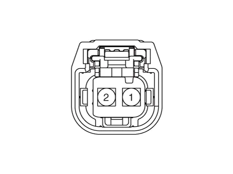
2.Disconnect the injector connector.
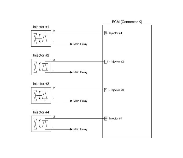
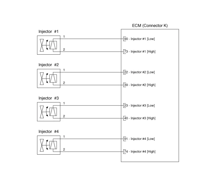
3.Measure resistance between the injector terminals 1 and 2.
4.Check that the resistance is within the specification.
Specification : Refer to "Specification"
1. Release the Residual Pressure in Fuel Line.(Refer to Fuel Delivery System - "Release Residual Pressure in Fuel Line")
2.Turn the ignition switch OFF and disconnect the battery negative (-) cable.
3. Remove the engine cover.(Refer to Engnie Mechanical System - "Engine Cover")
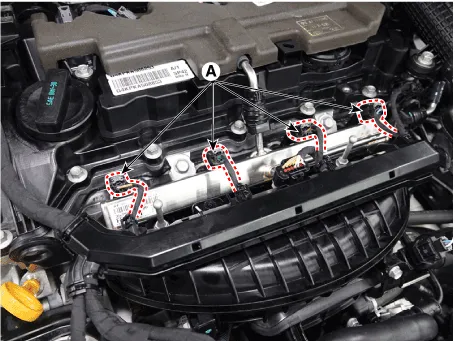
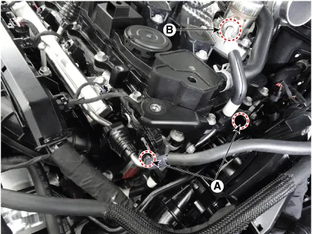
4. Disconnector the injector connector (A).
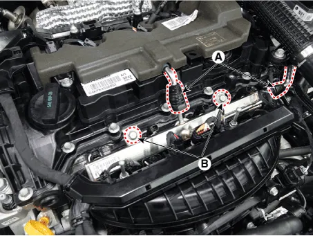
5. Disconnect the fuel delivery quick-connector (A).
6.Remove the delivery pipe mounting bolt (B).
Tightening torque :18.6 - 23.5 N.m (1.9 - 2.4 kgf.m, 13.7 - 17.3 lb-ft)

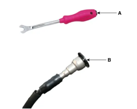
• Open the clamp cover (A) before disconnecting the quick-connector. (If the clip is applied)
• When removing the quick-connnector with the clip removing tool (A), be careful not to damage the plastic clip (B).
• If the clip is damaged, it can cause a fuel leak due to bad connection and could result in a fire.
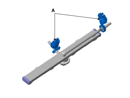
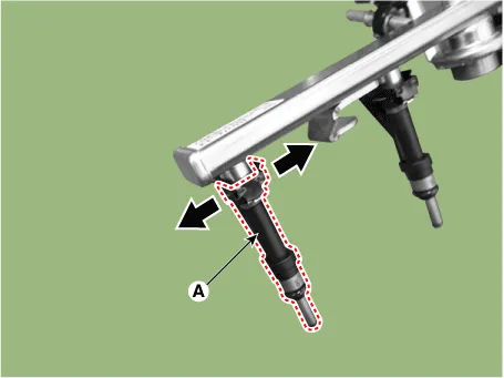
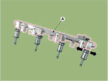
7. Release the fixing clip, and then separate the injector(A) from the delivery pipe.
1.Release the Residual Pressure in Fuel Line.(Refer to Fuel Delivery System - "Release Residual Pressure in Fuel Line")
2.Turn the ignition switch OFF and disconnect the battery negative (-) cable.
3. Remove the engine cover.(Refer to Engnie Mechanical System - "Engine Cover")
4. Remove the ignition coil connector (A).
5. Remove the head foam (B).
6. Remove the high pressure pump foam (A).
7. Remove the air cleaner assembly.(Refer to Engine Mechanical System - "Air Cleaner")
8. Remove the intercooler inlet hose.(Refer to Engine Mechanical System - "Intercooler")
9. Remove the high pressure fuel pipe braket installing bolt (A), and remove the flange nut (B).
Tightening torque :A : 9.8 - 11.7 N.m (1.0 - 1.2 kgf.m, 7.2 - 8.6 lb-ft)B : 26.4 - 32.3 N.m (2.7 - 3.3 kgf.m, 19.5- 23.8 lb-ft)
10. Remove the intake manifold.(Refer to Engine Mechanical System - "Intake Manifold")
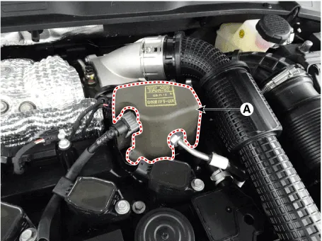
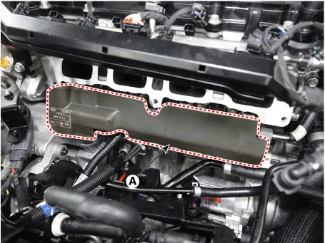
11.Disconnector the injector foam (A).
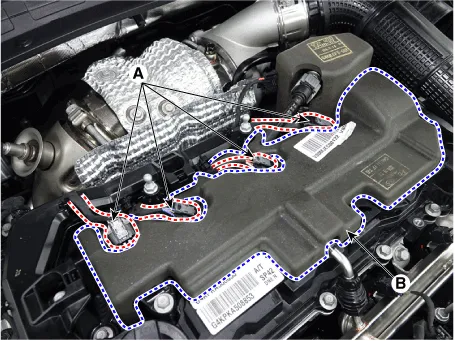
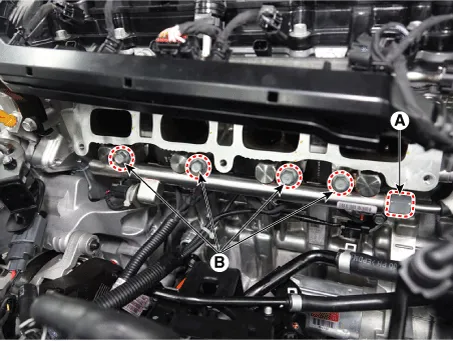
12. Remove the high pressure fuel pipe flange nut (A).
13. After remove the installing bolt (B), remove the delivery pipe & injector assembly.
Tightening torqueA : 26.4 - 32.3 N.m (2.7 - 3.3 kgf.m, 19.5- 23.8 lb-ft)B : 18.6 - 23.5 N.m (1.9 - 2.4 kgf.m, 13.7 - 17.3 lb-ft)
14. Disconnect the injector & rail sensor connector (A).
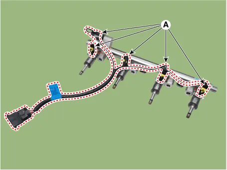
15.Remove the injector from the fuel rail (A) after releasing the fixing clip both side as shown below.
1.Install in the reverse order of removal.

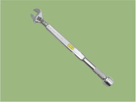
• When tightening the high pressure fuel pipe flange nut, use a torque wrench.
• Do not reuse the used high pressure fuel pipe.
• Careful not to deform the high pressure fuel pipe shape.
• Do not tilt the torque wrench when tightening the nut.
• Observe the work order and tightening torque when assembling.
• After assembly of the high pressure fuel pipe, check for leaks.
• When installing the high pressure fuel pipe, use a SST (09314-L1100).1) Refer to the following when reusing the injector
• When removing/reinstalling the injector, clean the cylinder head hole and the appearance.(Removal of carbon deposits and foreign substances using a brush)
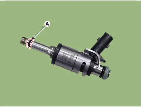
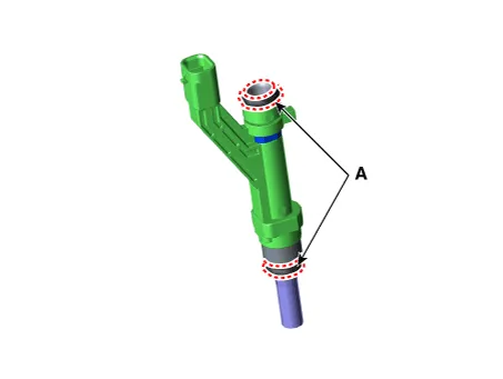
• Be careful not to apply oil/grease/lubricant to the combustion seal (A).
• Do not use the dropped part.
• When inserting the injector, be careful not to damage the injector tip.
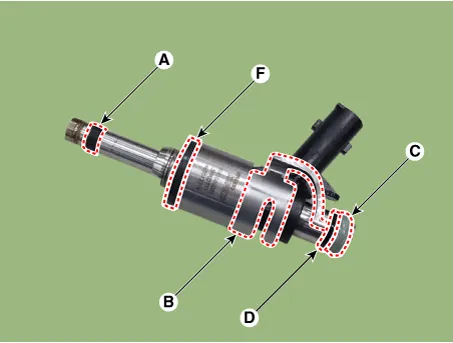
• Do not reuse the combustion seal (A), injector clip (B), O-ring (C), support disk (D), rubber washer (F).
• Be careful not to apply oil to combustion seal.
• Do not reuse the used injector O-ring.
• Apply engine oil to the injector O-ring.
• Be careful not to damage the end of the injector when inserting the injector.

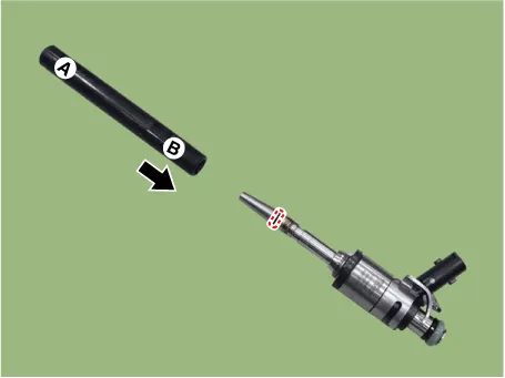
• Be sure to replace the combustion seal installed on the GDI injector following the below procedure to prevent possible leakage.
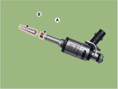
1.Remove the combustion seal (A).

• When removing the combustion seal, be careful not to damage the injector.
• When removing the combustion seal, use a nipper to cut it.

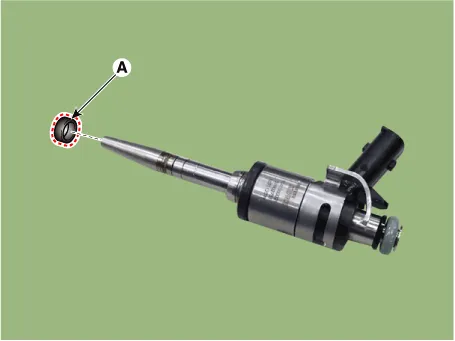
2.Before the assembly of the combustion seal the groove must be cleaned using a clean cloth.
3.Reinstall the combustion seal using the SST (09353-L1100).
(1)Place the combustion seal installing guide (A) on the tip of the injector not to damage the injector tip (B).
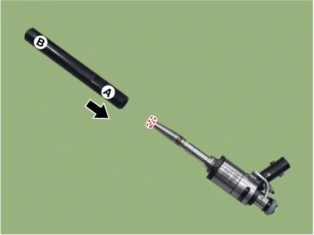
(2)Install the combustion seal (A) to the seal mounting guide.
(3)Input the seal to A direction of the installer, and push it to B direction until it reaches the combustion seal installation area.

• The complete assembly must not take longer than 2 to 3 seconds.
(4)Install the compressor (A) and disconnect it after rotating 3-4 times to left and right direction.
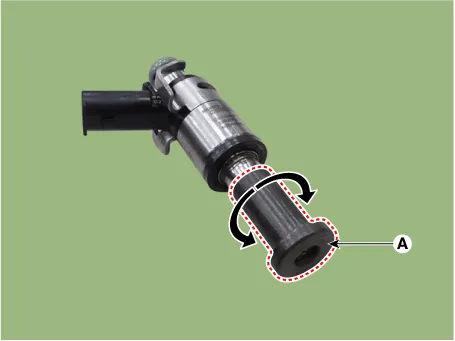
(5)Check the combustion seal (A) installation.

 Fuel Tank Pressure Sensor (FTPS)
- Description
Fuel Tank Pressure Sensor (FTPS) is a component of the evaporative
emission control system and is installed on the fuel tank, the fuel
pump, or the canister. It checks the purge c ...
 Purge Control Solenoid Valve (PCSV)
- Description
Purge Control Solenoid Valve (PCSV) is installed on the surge tank and
controls the passage between the canister and the vacuum line.The
evaporative gases gathered in the canister ...
Other information:
Hyundai Santa Cruz 2021-2025 Owners Manual: Vehicle Load Limit
Two labels on your driver’s door sill show
how much weight your vehicle was
designed to carry: the Tire and Loading
Information Label and the Certification
Label.
Before loading your vehicle, familiarize
yourself with the following terms for
determining your vehicle’s weight
ratings, from ...
Hyundai Santa Cruz 2021-2025 Owners Manual: Electrochromic Mirror with
Homelink System
Your vehicle may be equipped with
a Gentex Automatic-Dimming Mirror
with an Integrated HomeLink® Wireless
Control System.
During nighttime driving, this feature
will automatically detect and reduce
rearview mirror glare. The HomeLink®
Universal Transceiver allows you to
activate your garage ...
