Hyundai Santa Cruz: Indicators And Gauges / Instrument Cluster
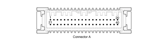
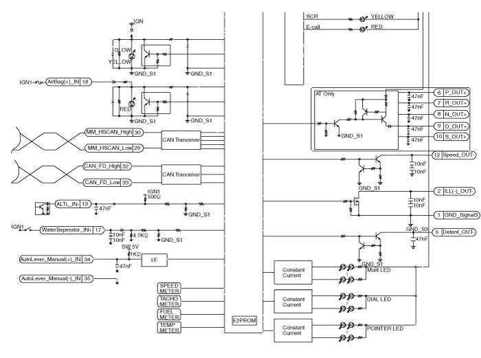
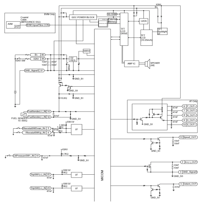
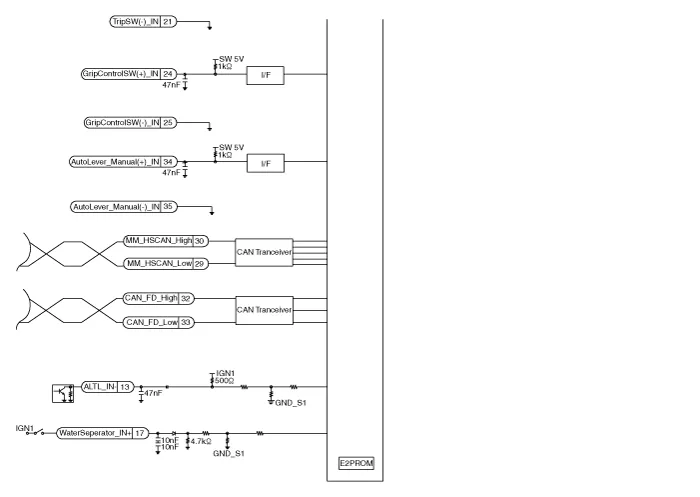
| No. | Connector A | No. | Connector |
| 1 | Ground 3 | 21 | Trip switch (-)_input |
| 2 | Illumination (-)_output | 22 | Trip switch 1 (+)_input |
| 3 | Rheostat switch (Down)_Input | 23 | Trip switch 2 (+)_input |
| 4 | Rheostat switch (Up)_Input | 24 | Grip control switch(+)_input |
| 5 | Dentent | 25 | Grip control switch(-)_input |
| 6 | P | 26 | - |
| 7 | R | 27 | - |
| 8 | N | 28 | - |
| 9 | D | 29 | M-CAN (Low) |
| 10 | S | 30 | M-CAN (High) |
| 11 | - | 31 | - |
| 12 | Vehicle speed_Output | 32 | CAN FD (High) |
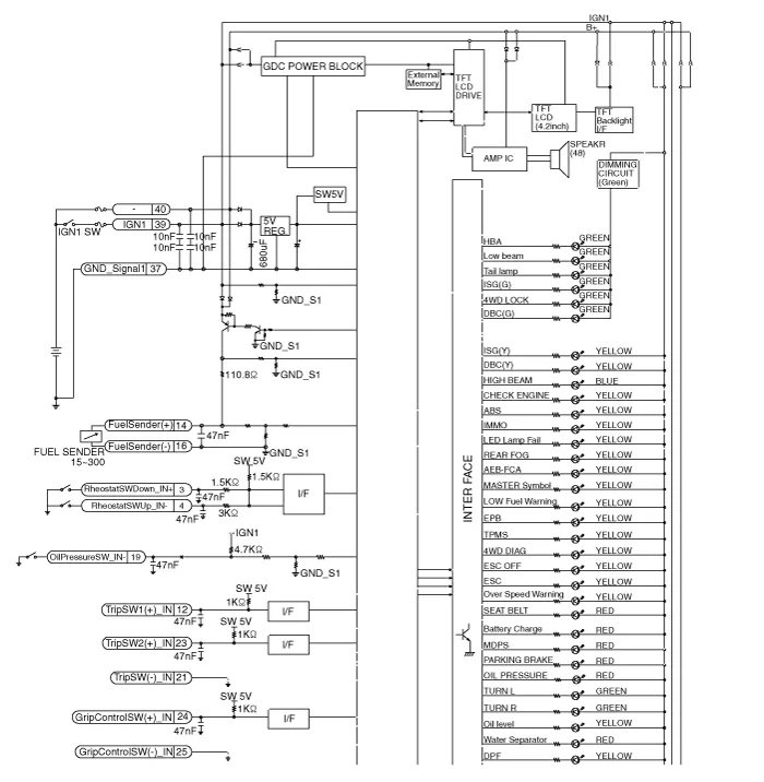
| 13 | AlTL_Input | 33 | CAN FD (Low) |
| 14 | Fuel sender (+)_Input | 34 | Auto lever (+)_Input |
| 15 | - | 35 | Auto lever (-)_Input |
| 16 | Fuel sender (-)_Input | 36 | - |
| 17 | Water separate_Input | 37 | Ground 1 |
| 18 | Airbag (+)_Input | 38 | - |
| 19 | Oilpressure switch_Input | 39 | IGN 1 |
| 20 | - | 40 | Battery (+) |
1.Disconnect the negative (-) battery terminal.
2.Remove the cluster fascia panel.(Refer to Body - "Cluster Fascia Panel")
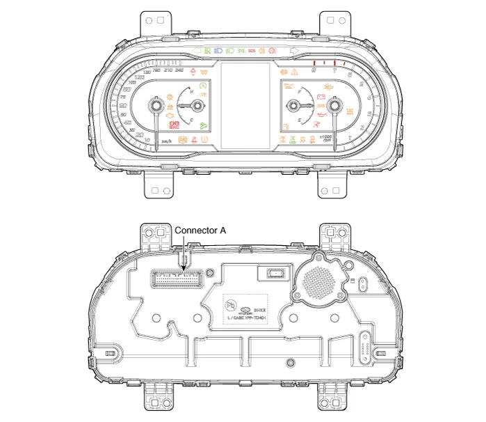
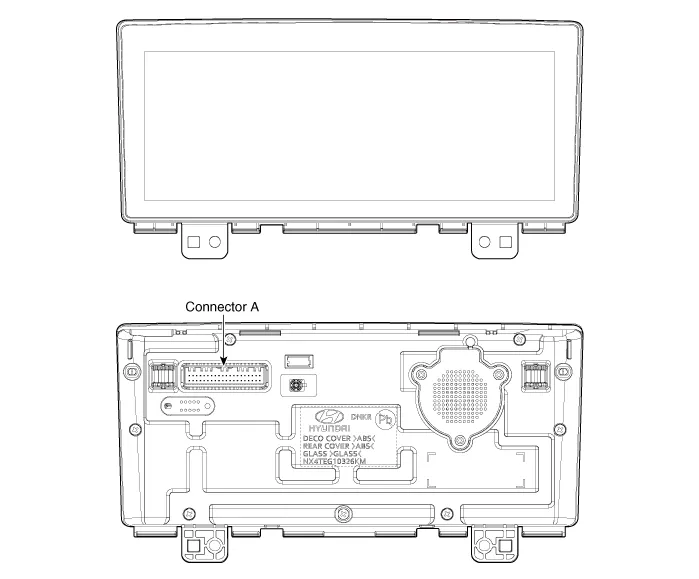
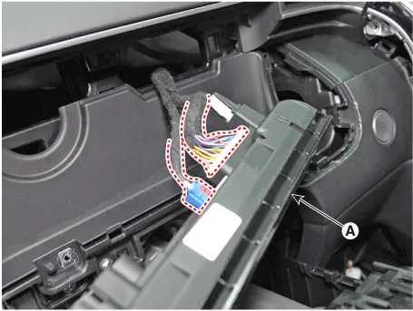
3.Remove the cluster (A) after loosening mounting screws.
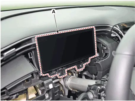
4.Disconnect cluster connecters and then remove the cluster (A).
1.Install the cluster assembly.
2.Install the cluster facia panel.
3.Connect the negative (-) battery terminal.

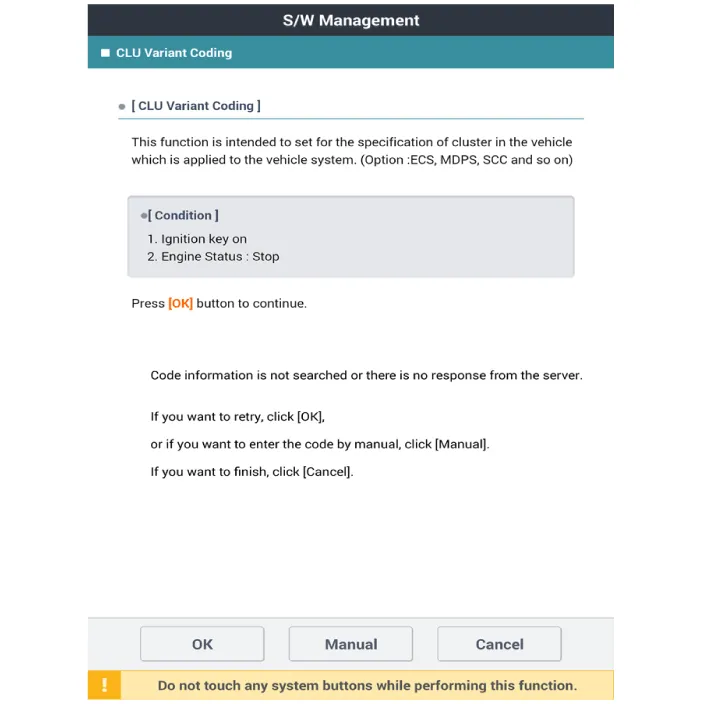
• Perform variant coding after exchanging the instrument cluster.
1.Check point (Warning indicator)
| No | Ref Symbol | Color | Name | Signal Input | Signal Control (Unit / Sensor) | Check Point | ||||
| 1 |
| Green | Turn Left | C-CAN | BCM |
| ||||
| 2 |
| Green | Turn Right | C-CAN | ||||||
| 3 |
| Green | Front Fog | C-CAN | BCM |
| ||||
| 4 |
| Blue | High Beam | C-CAN | BCM |
| ||||
| 5 |
| Green | Low Beam | C-CAN | BCM |
| ||||
| 6 |
| Green | Tail Lamp | C-CAN | BCM |
| ||||
| 7 |
| Green | Cruise | C-CAN | EMS |
| ||||
| 8 |
| Green | SET | C-CAN | EMS |
| ||||
| 9 |
| Red | Seat Belt | C-CAN | BCM |
| ||||
| 10 |
| Red | Air Bag | C-CAN | ACU |
| ||||
| 11 |
| Yellow | Trunk Open | C-CAN | BCM |
| ||||
| 12 |
| Red | Door Open | C-CAN | BCM |
| ||||
| 13 |
| Red | High Temperature | C-CAN | EMS |
| ||||
| 14 |
| Yellow | Immobilizer | C-CAN | SMK |
| ||||
| 15 |
| Yellow | ABS | C-CAN | ESC |
| ||||
| 16 |
| Yellow | EPB | C-CAN | EPB |
| ||||
| 17 |
| Yellow | ESC | C-CAN | ESC |
| ||||
| 18 |
| Yellow | ESC OFF | C-CAN | ESC |
| ||||
| 19 |
| Yellow | TPMS (Tread & Fail) | C-CAN | TPMS |
| ||||
| 20 |
| Yellow | Fuel Low | Hardwire | Fuel Sender |
| ||||
| 21 |
| Red | Parking Brake | C-CAN | BCM TCS EPB |
| ||||
| 22 |
| Yellow | Oil Pressure | Hardwire | Oil Pressure Sensor |
| ||||
| 23 |
| Red | Battery Charge | Hardwire | Battery Sensor |
| ||||
| 24 |
| Yellow | Check Engine | C-CAN | EMS |
| ||||
| 25 |
| Yellow | Low Washer | Hardwire | Water Level Sensor |
| ||||
| 26 |
| Green | AUTOHOLD (Green) | C-CAN | ESC |
| ||||
| Yellow | AUTOHOLD (Yellow) | C-CAN | ESC |
| |||||
| White | AUTOHOLD (White) | C-CAN | ESC |
| |||||
| 27 |
| Green White Yellow | LDWS | C-CAN | LDWS |
| ||||
| 28 |
| Green | Active ECO | Hardwire | ECO ON/OFF Switch |
| ||||
| 29 |
| Yellow | 4WD Diagnosis | C-CAN | 4WD Unit |
| ||||
| 30 |
| Yellow | 4WD LOCK | C-CAN | 4WD ECU |
| ||||
| 31 |
| Yellow | Glow | C-CAN | Glow Plug |
| ||||
| 32 |
| Red | EPS | C-CAN | EPS Unit |
| ||||
| 33 |
| Red | Water Seperator | C-CAN | Fuel filter water seperator sensor |
| ||||
| 34 |
| Green Yellow | DBC | C-CAN | TCU |
|


2.Check point (Gauge)
| No | Name | Signal Input | Signal Control (Unit/Sensor) | Check Point | ||||
| 1 | Speedometer | C-CAN | TCU, ABS |
| ||||
| 2 | Tachometer | C-CAN | EMS |
| ||||
| 3 | Cooling water temperature | C-CAN | EMS |
| ||||
| 4 | Fuel | Hardwire | Fuel sender |
|
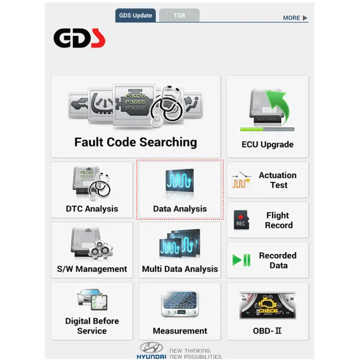
1.In the body electrical system, failure can be quickly diagnosed by using the vehicle diagnostic system.The diagnostic system provides the following information.
(1)Fault Code Searching : Checking failure and code number (DTC)
(2)Data Analysis : Checking the system input/output data state
(3)Actuation test : Checking the system operation condition
(4)S/W Management : Controlling other features including system option setting and zero point adjustment
2.If diagnose the vehicle by diagnostic tool, select "DTC Analysis" and "Vehicle".
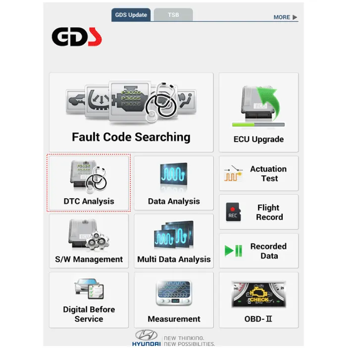
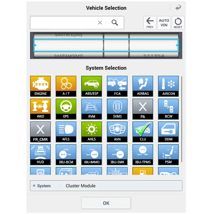
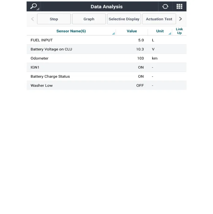
3.If check current status, select the "Data Analysis" and "Car model".
4.Select the 'CLU' to search the current state of the input/output data.
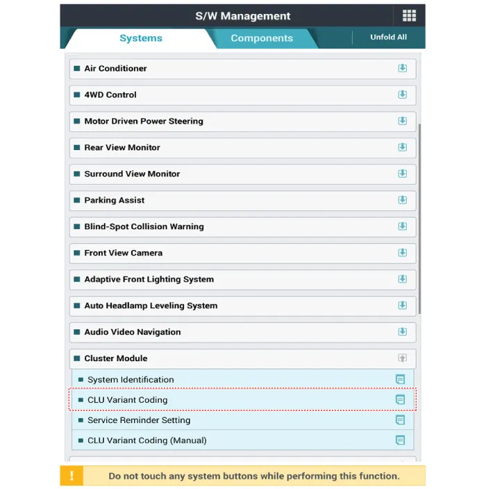
1.Connect the cable of diagnostic tool to the data link connector in driver side crash pad lower panel.
2.Select the 'S/W Management' and 'Car model'.

3.Select the 'Cluster Module' and 'CLU Variant Coding'.
 Troubleshooting
- Troubleshooting
Error ItemFailure SymptomInspection Items Detailed Inspections Relevant Parts/Components
Screen displayLCD-TFT screen does not turn on1)Connector attachments
2)Components
1 ...
 Power Door Locks
...
Other information:
Hyundai Santa Cruz 2021-2025 Owners Manual: Theft-alarm System
This system helps to protect your vehicle
and valuables. The horn will sound and
the hazard warning lights will blink
continuously if any of the following
occur:
- A door is opened without using the
remote key or smart key.
- The tailgate is opened without using
the remote key or smart key.
- ...
Hyundai Santa Cruz 2021-2025 Owners Manual: Tires and Wheels
NOTICE
It is permissible to add 3 psi to the standard tire pressure
specification if colder
temperatures are expected soon.
Tires typically lose 1psi (7kPa) for every 12°F temperature drop. If extreme
temperature variations are expected, recheck your tire pressure as necessary
to
ke ...
