Hyundai Santa Cruz: Intake And Exhaust System / Turbocharger & Exhaust Manifold
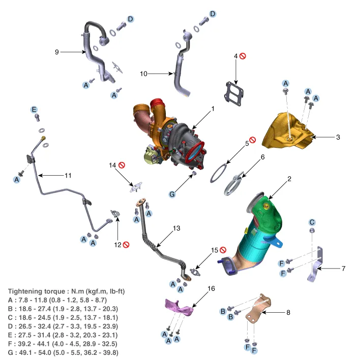
1. Turbocharger & exhaust manifold
2. Warm-up catalytic converter (WCC)
3. Upper heat protector
4. Turbo manifold module gasket
5. Warm-up catalytic converter (WCC) gasket
6. V-calmp
7. Warm-up catalytic converter (WCC) upper bracket
8. Warm-up catalytic converter (WCC) lower bracket
9. Turbocharger water feed pipe
10. Turbocharger water drain pipe
11. Turbocharger oil feed pipe
12. Turbocharger oil feed pipe gasket
13. Turbocharger oil drain pipe
14. Turbocharger oil drain pipe upper gasket
15. Turbocharger oil drain pipe lower gasket
16. Lower heat protector

• To prevent scalding by the hot exhaust parts, wait until the engine cools down to room temperature.

• Use fender covers to avoid damaging painted surfaces.
• When handling the metal gasket, be careful not to fold or damage the surface.
• To avoid damage, disconnect the wiring connectors carefully.
• Replace all gaskets with new ones. Do not reuse.
1.Disconnect the negative battery terminal.
2.Remove the engine cover.(Refer to the Engine And Transaxle Assembly - "Engine Cover")
3.Remove the engine room under cover.(Refer to the Engine And Transaxle Assembly - "Engine Room Under Cover")
4.Remove the front muffler.(Refer to the Intake And Exhaust System - "Muffler")
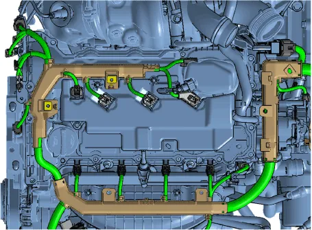
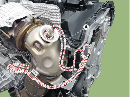
5.Disconnect the engine wiring connectors and harness clamps around the turbocharger & exhaust manifold and then remove the connector brackets and wiring protector.
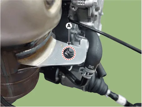
6.Disconnect the heated oxygen sensor connector (A) from wiring bracket.
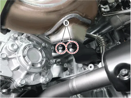
7.Remove the warm up catalytic converter (WCC) mounting nut (A) and warm up catalytic converter (WCC) bracket mounting nuts (B).
Tightening torque : Nut (A) : 18.6 - 24.5 N.m (1.9 - 2.5 kgf.m, 13.7 - 18.1 lb-ft)Nuts (B) : 39.2 - 44.1 N.m (4.0 - 4.5 kgf.m, 28.9 - 32.5 lb-ft)
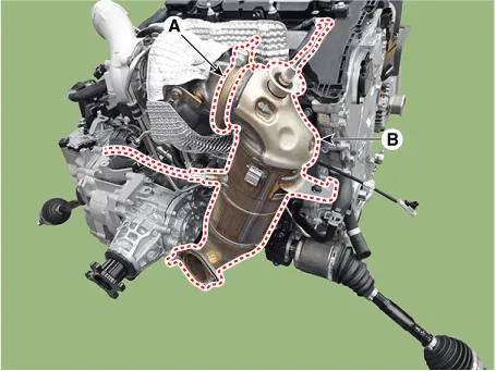
8.Remove the V-clamp (A), and then remove the warm up catalytic converter (WCC) (B).
Tightening torque: 13.7 - 16.7 N.m (1.4 - 1.7 kgf.m, 10.1 - 12.3 lb-ft)
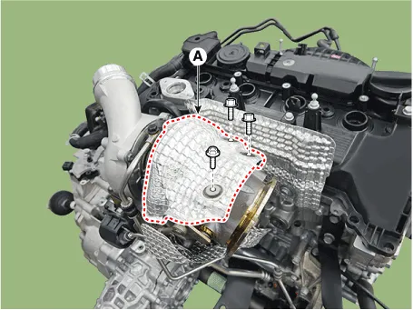
9.Remove the upper heat protector (A).
Tightening torque :7.8 - 11.8 N.m (0.8 - 1.2 kgf.m, 5.8 - 8.7 lb-ft)
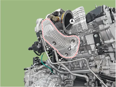
10.Remove the lower heat protector (A).
Tightening torque :7.8 - 11.8 N.m (0.8 - 1.2 kgf.m, 5.8 - 8.7 lb-ft)
11.Remove the air duct and air intake hose.(Refer to the Intake And Exhaust System - Air Cleaner")
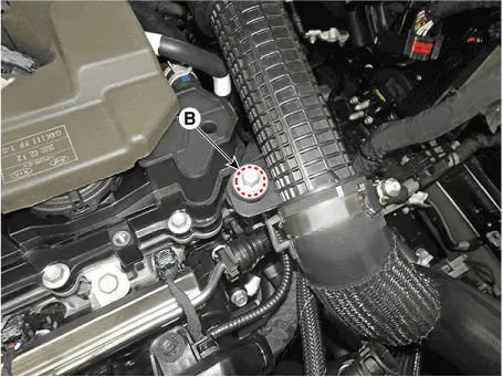
12.Remove the intercooler inlet hose & pipe (A) after loosen the bolt (B).
Tightening torque :14.7 - 19.6 N.m (1.5 - 2.0 kgf.m, 10.8 - 14.5 lb-ft)


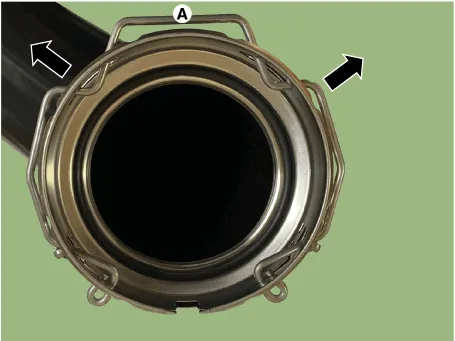
1)When disconnect the intercooler inlet hose, pull out the quick connector clamp (A) in the direction of the arrow as shown below.
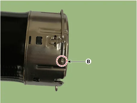
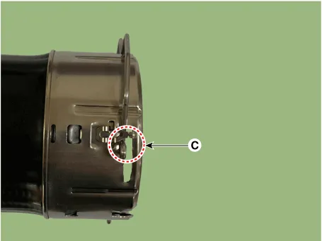
2)Move the quick connector clamp from position (B) to position (C) as shown below and pull out the quick connector hose.
13.Disconnect the hose (A), and then remove the air intake hose (B).
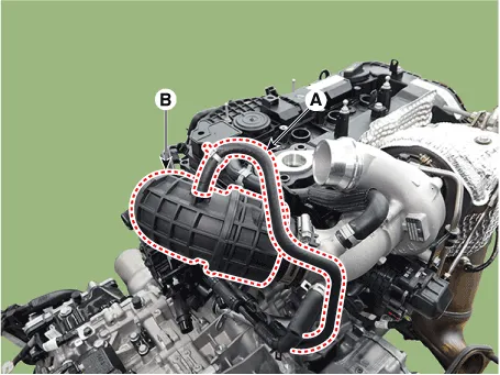
14.Disconnect the breather hose (A).
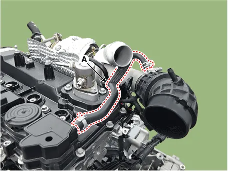
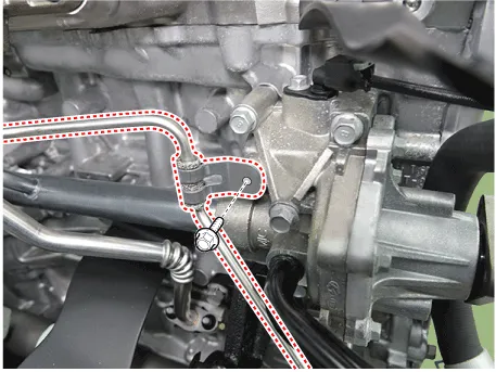
15.Remove the oil feed pipe (A).
Tightening torque :Eyebolt : 27.5 - 31.4 N.m (2.8 - 3.2 kgf.m, 20.3 - 23.1 lb-ft)Nut : 7.8 - 11.8 N.m (0.8 - 1.2 kgf.m, 5.8 - 8.7 lb-ft)Bolt : 7.8 - 11.8 N.m (0.8 - 1.2 kgf.m, 5.8 - 8.7 lb-ft)
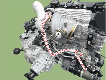
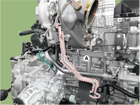
16.Remove the oil drain pipe (A).
Tightening torque :7.8 - 11.8 N.m (0.8 - 1.2 kgf.m, 5.8 - 8.7 lb-ft)
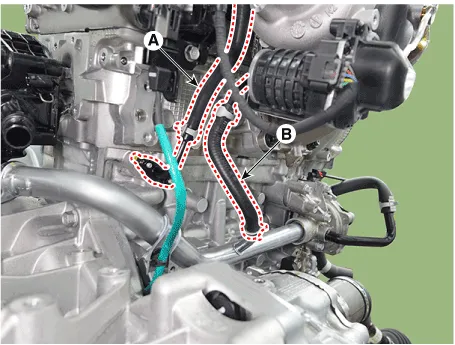
17.Disconnect the turbocharger water feed pipe & hose (A) and turbocharger water drain pipe & hose (B).
Tightening torque :7.8 - 11.8 N.m (0.8 - 1.2 kgf.m, 5.8 - 8.7 lb-ft)
18.Remove the turbocharger & exhaust manifold (A) with the gasket (B).
Tightening torque: 49.0 - 53.9 N.m (5.0 - 5.5 kgf.m, 36.2 - 39.8 lb-ft)
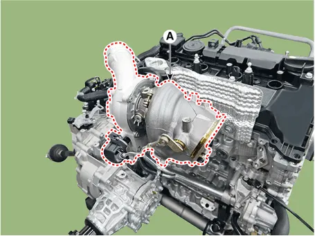
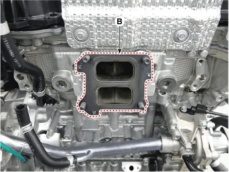

• Do not reuse the turbocharger & exhaust manifold gasket.
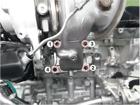
• When installing, pretighten the nuts in the order shown below and then completely tighten the bolts to specified torque in the order.
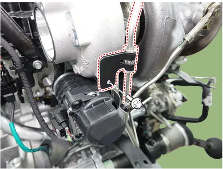
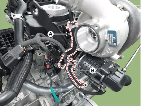
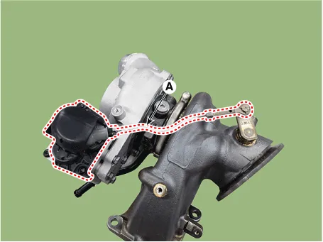
19.Remove the electric waste gate actuator (EWGA) (A) after loosening the mounting bolts.
Tightening torque :11.8 - 13.7 N.m (1.2 - 1.4 kgf.m, 8.7 - 10.1 lb-ft)
20.Install in the reverse order of removal.

• Adjust the electric waste gate actuator (EWGA) rod.(Refer to Engine Control / Fuel System - "Electric Waste Gate Actuator (EWGA)")
 Intake Manifold
- Components
1. Intake manifold2. Intake manifold stay3. Electronic throttle contorl (ETC) gasket4. Electronic throttle contorl (ETC)5. Purge control solenoid valve (PCSV) and hoses6. Intake man ...
 Turbocharger
- Removal and Installation
1.Remove the turbocharger & exhaust manifold(Refer to Intake and Exhaust System - "Turbocharger & Exhaust Manifold")
- On-vehicle Inspection
Turbocharger Dia ...
Other information:
Hyundai Santa Cruz (NX4A OB) 2021-2025 Service Manual: Repair procedures
- Adjustment
1.In the body electrical system, failure can be quickly diagnosed by
using the vehicle diagnostic system (diagnostic tool).The diagnostic
system (diagnostic tool) provides the following information.(1)Fault Code Searching : Checking failure and code number (DTC)
(2)Data Analysi ...
Hyundai Santa Cruz (NX4A OB) 2021-2025 Service Manual: Repair procedures
- Removal
1.Disconnect the negative (-) battery terminal.
2.Remove the inside rear view mirror cover (A) and (B).
3.Disconnect the inside rear view mirror connector (A).
4.Loosen the mounted screws and push the ECM mirror base upward to remove the ECM mirror assembly (A).
- Inspection ...
