Hyundai Santa Cruz: Engine Control System / Engine Coolant Temperature Sensor (ECTS)
| Temperature (°C, °F) | Resistance (kΩ) |
| -40 (-40) | 41.74 - 54.54 |
| -30 (-22) | 23.54 - 29.94 |
| -20 (-4) | 14.13 - 16.83 |
| -10 (14) | 8.39 - 10.22 |
| 0 (32) | 5.28 - 6.30 |
| 10 (50) | 3.42 - 4.01 |
| 20 (68) | 2.31 - 2.59 |
| 30 (86) | 1.55 - 1.76 |
| 40 (104) | 1.08 - 1.20 |
| 50 (122) | 0.77 - 0.85 |
| 60 (140) | 0.56 - 0.61 |
| 70 (158) | 0.42 - 0.45 |
| 80 (176) | 0.31 - 0.33 |
| 90 (194) | 0.24 - 0.25 |
| 100 (212) | 0.184 - 0.192 |
| 110 (230) | 0.145 - 0.149 |
| 120 (248) | 0.114 - 0.119 |
| 130 (266) | 0.091 - 0.095 |
| 140 (284) | 0.073 - 0.077 |
| 150 (302) | 0.059 - 0.063 |


1.Turn the ignition switch OFF.
2.Remove the ECTS.(Refer to "Removal")
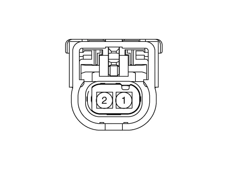
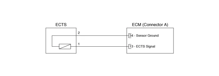
3.After immersing the thermistor of the sensor into engine coolant, measure resistance between the ECTS signal terminals and ground terminals.
4. Check that the resistance is within the specification.
Specification : Refer to "Inspection"
1. Turn the ignition switch OFF and disconnect the battery negative (-) cable.
2. Remove the air cleaner assembly.(Refer to Engine Mechanical System - "Air Cleaner")
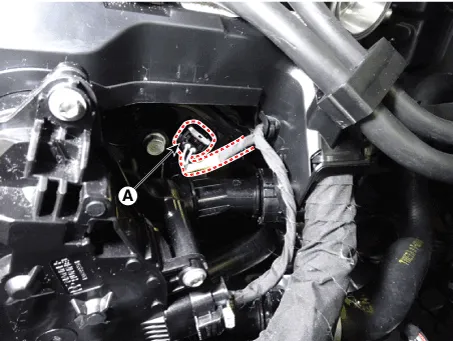
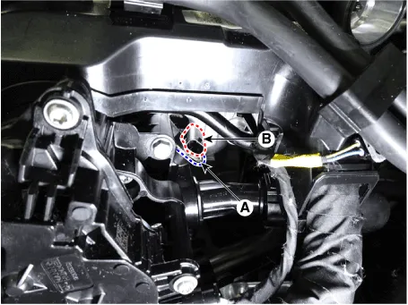
3. Disconnect the engine coolant temperature sensor connector (A).
4. Disconnect the fixing clip (A), and remove the engine coolant temperature sensor (B).
1. Turn the ignition switch OFF and disconnect the battery negative (-) cable.
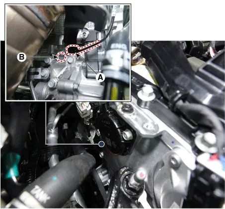
2. Disconnect the engine coolant temperature sensor connector (A).
3. After removing the installation bolts (B), remove the engine coolant temperature sensor.
Tightening torque :9.8 - 11.7 N.m (1.0 - 1.2 kgf.m, 7.2 - 8.6 lb-ft)
1. Turn the ignition switch OFF and disconnect the battery negative (-) cable.
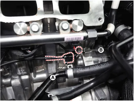
2.Remove the intake manifold.(Refer to Engine Mechanical System - "Intake Manifold)
3. Disconnect the engine coolant temperature sensor connector (A).
4. After removing the installation bolts (B), remove the engine coolant temperature sensor.
Tightening torque :9.8 - 11.7 N.m (1.0 - 1.2 kgf.m, 7.2 - 8.6 lb-ft)

• Install the component to the specified torques.
• Note that internal damage may occur when the component is dropped. If the component has been dropped, inspect before installing.
• Replenish the engine coolant.
1. Install in the reverse order of removal.
2.Supply the Engine Coolant.(Refer to Engine Mechanical System - "Coolant System")
 Ambient Temperature Sensor (ATS)
- Description
Installed on the front-end module, the Ambient Temperature Sensor (ATS)
senses the ambient temperature. ECM receives the intake air temperature
and ambient air temperature at the ...
 Crankshaft Position Sensor (CKPS)
- Description
Crankshaft Position Sensor (CKPS) detects the crankshaft position and
is one of the most important sensors of the engine control system. If
there is no CKPS signal input, the engi ...
Other information:
Hyundai Santa Cruz 2021-2025 Owners Manual: Air bag collision sensors
WARNING
To reduce the risk of an air bag
deploying unexpectedly and causing
serious injury or death:
Do not hit or allow any objects to
impact the locations where air bags
or sensors are installed.
Do not perform maintenance on or
around the air bag sensors. If the
location or angle of ...
Hyundai Santa Cruz 2021-2025 Owners Manual: What to expect after an air bag
inflates
After a frontal or side air bag inflates,
it will deflate very quickly. Air bag
inflation will not prevent the driver from
seeing out of the windshield or being
able to steer as it will immediately start
deflating. Curtain air bags may remain
partially inflated for some time after they
deploy ...
