Hyundai Santa Cruz: Front Axle Assembly / Front Hub / Knuckle / Tone Wheel
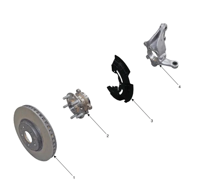
1. Front brake disc
2. Front hub assembly
3. Dust cover
4. Front knuckle

• When lifting a vehicle using a lift, be careful not to damage the lower parts of the vehicle (floor under cover, fuel filter, fuel tank, canister).(Refer to General Information - "Lift and Support Points")
1.Loosen the front wheel nuts slightly.Raise the vehicle, and make sure it is securely supported.
2.Remove the front wheel and tire.(Refer to Suspension System - "Wheel")
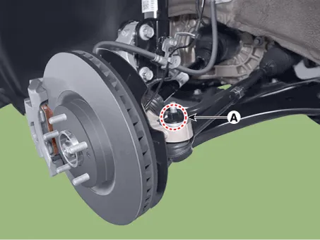
3.Loosen the tie rod end ball joint nut (A).
Tightening torque: 98.0 - 117.6 N.m (10.0 - 12.0 kgf.m, 72.3 - 86.7 lb-ft)
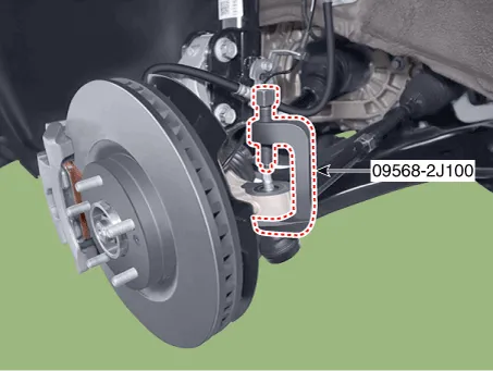
4.Remove the tie rod end ball joint using the SST (09568-2J100).
5.Remove the front brake caliper.(Refer to Brake System - "Front Disc Brake")
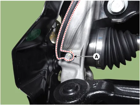
6.Disconnect the wheel speed sensor (A) from the knuckle after loosening the mounting bolt.
Tightening torque : 6.9 - 10.8 N.m (0.7 - 1.1 kgf.m, 5.1 - 8.0 lb-ft)
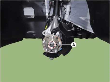
7.Loosen the caulking nut (A) from the front hub.
Tightening torque : 294.2 - 313.8 N.m (30.0 - 32.0 kgf.m, 217.0 - 231.5 lb-ft)

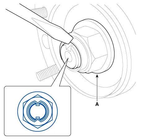
• The driveshaft lock nut (A) should be replaced with new ones.
• After installation driveshaft lock nut, stake the lock nut using a chisel and hammer as shown in the illustration below.
Caulking depth : 1.5 mm (0.591 in.)
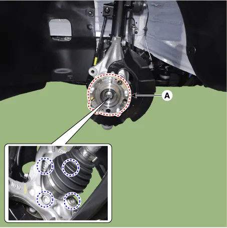
8.Remove the front hub bearing (A) after loosening the mounting bolts.
Tightening torque : 127.5 - 147.1 N.m (13.0 - 15.0 kgf.m, 94.0 - 108.5 lb-ft)
9.Remove the dust cover (A).
Tightening torque : 3.9 - 5.9 N.m (0.4 - 0.6 kgf.m, 2.9 - 4.3 lb-ft)
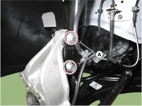
10.Loosen the front strut assembly mounting bolts and nuts (A) from the front axle.
Tightening torque :235.2 - 254.8 N.m (24.0 - 26.0 kgf.m, 173.6 - 188.0 lb-ft)
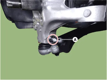
11.Loosen the front lower arm mounting bolt and nut (A).
Tightening torque: 98.0 - 117.6 N.m (10.0 - 12.0 kgf.m, 72.3 - 86.7 lb-ft)
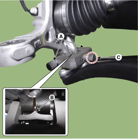
12.Remove the lower arm from the knuckle by using the SST (09568-4R100).
(1)Install the support bolt (A) from lower arm bolt hole.
(2)Install the support body (B) from front axle.
(3)Tighten the bolt (C).
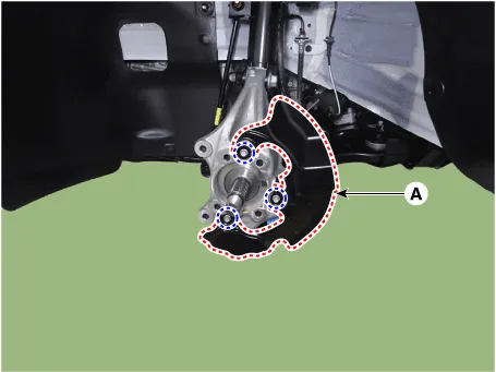
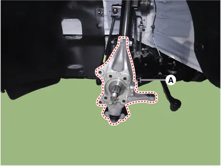
13.Remove the front knuckle (A).
1.Check the hub for cracks and the splines for wear.
2.Check the brake disc for scoring and damage.
3.Check the knuckle for cracks.
4.Check the bearing for cracks or damage.
1.To install, reverse the removal procedures.
2.Check the alignment.(Refer to Suspension System - "Alignment")


Other information:
Hyundai Santa Cruz (NX4A OB) 2021-2025 Service Manual: Air Cleaner
- Components
1. Air cleaner body2. Air cleaner cover3. Intake hose4. Air cleaner element5. Air duct6. Dual purge ejector
- Removal and installation
Air Cleaner Assembly
1.Disconnect the battery negative terminal.
2.Remove the engine cover.(Refer to Engine And Transaxle Assembly - “ ...
Hyundai Santa Cruz 2021-2025 Owners Manual: Tires and Wheels
NOTICE
It is permissible to add 3 psi to the standard tire pressure
specification if colder
temperatures are expected soon.
Tires typically lose 1psi (7kPa) for every 12°F temperature drop. If extreme
temperature variations are expected, recheck your tire pressure as necessary
to
ke ...
