Hyundai Santa Cruz: Air Bag - Supplemental Restraint system / Where are the Air Bags?
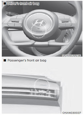
Driver’s and passenger’s front air bags
Your vehicle is equipped with a Supplemental Restraint System (SRS) as well as lap/shoulder belts at both the driver and passenger seating positions.
The SRS consists of air bags which are located in the center of the steering wheel and the passenger’s side front panel pad above the glove box.
The air bags are labeled with the letters “AIR BAG” embossed on the pad covers.
The purpose of the SRS is to provide the vehicle’s driver and front passengers with additional protection than that offered by the seat belt system alone in case of a frontal impact of sufficient severity.
The SRS uses sensors to gather information about the driver’s and front passenger's seat belt usage and impact severity.
The seat belt buckle sensors determine if the driver and front passenger's seat belts are fastened. These sensors provide the ability to control the SRS deployment based on whether or not the seat belts are fastened, and how severe the impact is.
The advanced SRS offers the ability to control the air bag inflation within two levels. A first stage level is provided for moderate-severity impacts. A second stage level is provided for more severe impacts.
According to the impact severity, and seat belt usage, the SRS Control Module (SRSCM) controls the air bag inflation. Failure to properly wear seat belts can increase the risk or severity of injury in an accident.
WARNING
To reduce the risk of serious injury or death from inflating front air bags, take the following precautions:
- Seat belts must be worn at all times to help keep occupants positioned properly.
- Move your seat as far back as possible from front air bags, while still maintaining control of the vehicle.
- Never lean against the door or center console.
- Do not allow the front passenger to place their feet or legs on the dashboard.
- No objects (such as crash pad cover, mobile phone holder, cup holder, air fresheners or stickers) should be placed over or near the air bag modules on the steering wheel, instrument panel, windshield glass, and the front passenger’s panel above the glove box. Such objects could cause harm if the vehicle is in a crash severe enough to cause the air bags to deploy.
- Do not attach any objects on the front windshield and inside mirror.
 Air Bag - Supplemental Restraint system
1. Driver’s front air bag
2. Passenger’s front air bag
3. Side air bag
4. Curtain air bag
This vehicle is equipped with a Supplemental Air Bag System for the driver’s
seat and
front passenger ...
 Side air bags
Your vehicle is equipped with a side air
bag in each front seat. The purpose of
the air bag is to provide the vehicle’s
driver and the front passenger with
additional protection than that offer ...
Other information:
Hyundai Santa Cruz (NX4A OB) 2021-2025 Service Manual: Vacuum Pump
- Removal
[G 2.5 T-GDI Theta lll]
1.Disconnect the (-) battery terminal.
2.Remove the fastener (A).
3.Remove the clip (A), then disconnect the vacuum pump hose (B).
4.Disconnect the vacuum pump connector (A).
5.Remove the bolts, then remove the vacuum pump assembly (A).Tightening torq ...
Hyundai Santa Cruz 2021-2025 Owners Manual: Battery replacement
If the Smart Key is not working properly,
try replacing the battery with a new one.
Battery Type: CR2032
To replace the battery:
Battery Type: CR2032
To replace the battery:
1. Remove the mechanical key.
2. Use a slim tool or utility blade to pry
open the cover of the smart key. Use
caution not ...
