Hyundai Santa Cruz: SRSCM / Front Impact Sensor (FIS)
• The front impact sensors (FIS) are installed on the upper of the side panel in Front End Module (FEM). They are remote sensors that detect acceleration due to a collision at their mounting locations.
• The primary purpose of the Front Impact Sensor (FIS) is to provide an indication of a collition. The Front Impact Sensor(FIS) sends acceleration data to the SRSCM.
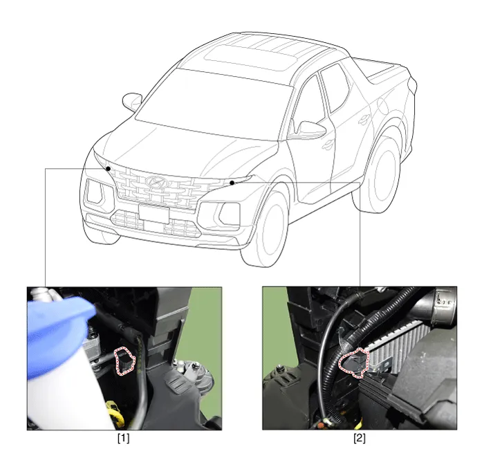
1. Front Impact Sensor (FIS) [RH]
2. Front Impact Sensor (FIS) [LH]
1.Disconnect the battery negative terminal.

• After disconnecting the cables, wait at least 3 minutes.
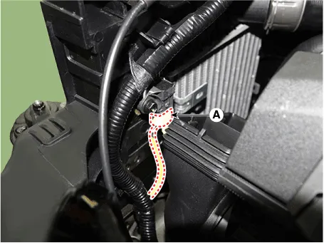
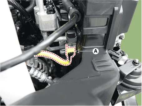
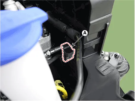
2.Disconnect the front impact sensor connector (A).
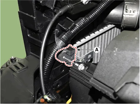
3.Loosen the mounting bolt, remove the front impact sensor (A).
Tightening torque :10.3 - 12.6 N·m (1.1 - 1.3 kgf·m, 7.6 - 9.3 lbf·ft)
1.Install in the reverse of the removal.
2.After installing the FIS, confirm proper system operation.

• Switch ON the ignition. The SRS indicator light should turn on for about six seconds and then off.
 SRS Control Module (SRSCM)
- Description
The primary purpose of the SRSCM (Supplemental Restraints System
Control Module) is to discriminate between an event that warrants
restraint system deployment and an event that do ...
 Side Impact Sensor (SIS)
- Description
1.The Side Impact Sensor (SIS) system consists of two kinds of side
impact sensor which are installed at each center of the front door
module (left and right) and two rear sensors ...
Other information:
Hyundai Santa Cruz (NX4A OB) 2021-2025 Service Manual: Crash Pad Center Panel
- Component Location
1. Crash pad center panel
- Replacement
• When prying with a flat-tip screwdriver, wrap it with protective
tape, and apply protective tape around the related parts, to prevent
damage.
• Put on gloves to protect your hands.
& ...
Hyundai Santa Cruz (NX4A OB) 2021-2025 Service Manual: Front Hub / Knuckle / Tone Wheel
- Components
1. Front brake disc2. Front hub assembly3. Dust cover4. Front knuckle
- Removal
• When lifting a vehicle using a lift, be careful not to damage
the lower parts of the vehicle (floor under cover, fuel filter, fuel
tank, canister).(Refer to General I ...
