Hyundai Santa Cruz: Lighting System / Turn Signal Lamp

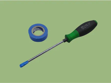
• When removing with a flat-tip screwdriver or remover, wrap protective tape around the tools to prevent damage to components.
• Put on gloves to prevent hand injuries.
1.Disconnect (-) battery terminal.
2.Remove the outside rear view mirror.(Refer to Body - "Outside Rear View Mirror")
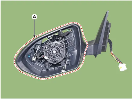
3.Using a fastener remover (C), remove the mirror (A) as illustration below.
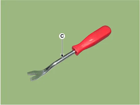
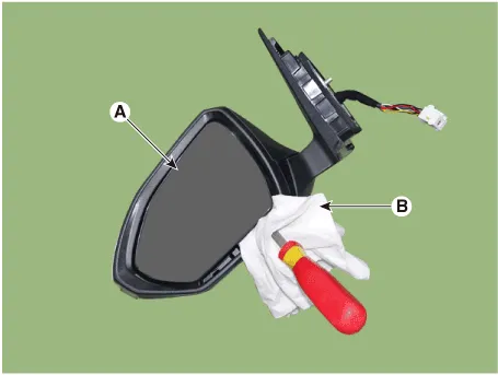

• Protect mirror from removing tool with cloth (B) wrapped.
• Be careful not to damage mirror and mirror housing during removing process.
• Apply force around the center of mirror because to apply force the end of mirror will break it.
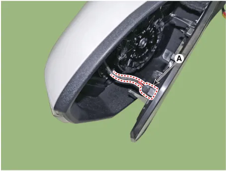
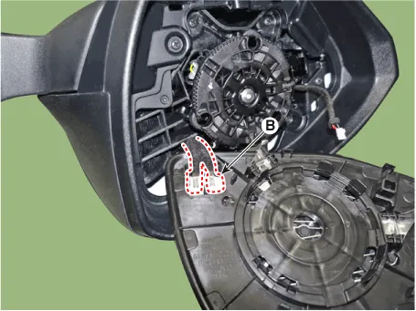
4.isconnect heat wire connectors (B) and BCW warning indicator connector (A).
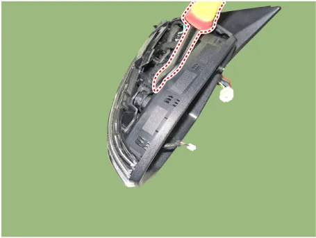
5.Remove the scalp.
1)Attach protection tape at the end of the screw driver.
2)Insert screw driver in where you can see the back of scalp.
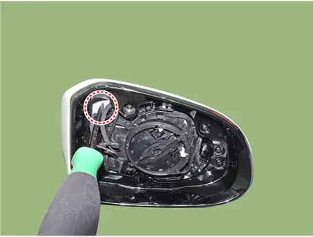

• When inserting screw driver, avoid to touch internal wires in the mirror housing.
3)Hold the mirror assembly with one hand and hold the screwdriver with the other hand and strike it vertically as shown illustration below.
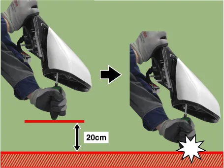

• It is the way that screw driver strikes inner side of scalp cover to remove.
• Lift screw driver and door mirror assembly about 20cm height from floor then smash them vertically.
• Scalp is thrown and removed because screw driver push the back of scalp cover to remove.
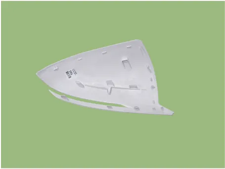
• After removing the scalp, make sure that the clip and hook on the back of the scalp are not damaged.
• If clips and hooks are damaged, replace the scalp with a new one as noise may occur in driving.
6.Remove the fornt housing cover (A) after loosening mounting screws.

• Insert flat-tip screwdriver between housing cover and housing as shown illustration below.
1.Disconnect the negative (-) battery terminal.
2.Remove the front wheel guard.(Refer to Body - "Front Wheel Guard")
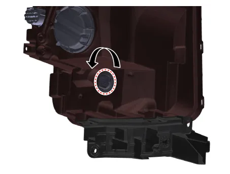
3.Remove the turn signal lamp after turning in the counterclockwise direction.
1.Install the outside rear view mirror and connect the connector.
Tightening torque :6.9 - 10.8 N.m (0.7 - 1.1 kgf.m, 5.0 - 8.0 lb-ft)
2.Connect the negative (-) battery terminal.
1.Install the front turn signal lamp.
2.Install the front wheel guard.
3.Connect the negative (-) battery terminal.
 Side Mark Lamp
- Removal
1.Disconnect the negative (-) battery terminal.
2.Remove the front bumper assembly.(Refer to Body - "Front Bumper Assembly")
3.Disconnect the side mark lamp connector (A).
4.Loosen ...
 Back-up Lamps
- Removal
1.Disconnect (-) battery terminal.
2.Remove the rear bumper assembly.(Refer to Body - "Rear Bumper Assembly")
3.Disconnect the back-up lamp connector (A) and remove the mounting clips ...
Other information:
Hyundai Santa Cruz (NX4A OB) 2021-2025 Service Manual: Troubleshooting
- Troubleshooting
Trouble symptomProbable causeRemedy
Engine will not start or is hard to start (Cranks OK)Ignition lock switchInspect ignition lock switch, or replace as required
Ignition coilInspect ignition coil, or replace as required
Spark plugsInspect spark plugs, or replace as required
...
Hyundai Santa Cruz (NX4A OB) 2021-2025 Service Manual: Description and Operation
- Description
The cruise control system is engaged by the cruise "ON/OFF" main switch
located on right of steering wheel column. The system has the
capability to cruise, coast, accelerate and resume speed.It also has a
safety interrupt, engaged upon depressing brake or shifting select
lev ...
